
Page 974 - 5G Basics - Core Network Aspects
P. 974
2 Transport aspects
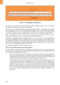
SFDC=0 New Q, K, R
DTU DTU DTU DTU DTU DTU RMC DTU DTU DTU DTU
Data symbol Data symbol Data symbol Data symbol RMC symbol Data symbol Data symbol Data symbol
d_SRA scaling factor,
new b i, g i, B D, B DR
Figure 13-3 – Timing diagram of SRA transition
The receiver shall not initiate a new SRA procedure until the ongoing procedure, if any, has completed
successfully or has failed due to rejection or has timed-out.
The timeout for OLR request (high priority command) is specified in Table 11-2. This timeout serves for both
the eoc response (see Table 11-19) and the RMC response (SRA-R). If the sourcing FTU hasn't received SRA-
R during this timeout and it has received at least the last RMC prior to expiration of this timeout with
errors, the sourcing FTU shall wait an additional 100 ms for SRA-R before initiating another SRA request.
NOTE – The response time of the FTU needs to take into account that, assuming no errors, the SRA-R should be
received by the sourcing FTU at least once during the 50 ms timeout specified in Table 11-2.
The rules for repeating SRA requests are specified in clause 11.2.1.3. However, if the receiver extended the
timeout by the additional 100 ms as specified above, it shall also not repeat the SRA request in this
extended timeout. All SRA requests relating to a given operation interval (NOI or DOI) with the same SCCC
count shall be considered identical. The transmitter shall discard request with SCCC equal or lower than the
one currently in use, taking SCCC wraparound into account.
The range of valid initial values of SFDC shall be from 4 to 15.
13.2.1.1.6 Retransmission of DTUs across SRA transitions
Retransmissions of erroneous DTUs shall be supported across the SRA transition, by re-framing with the
new DTU control parameters the data and/or management frame(s) previously transmitted with the old
DTU parameters. This shall take place as follow:
– In case of DTU size increase, the transmitter shall construct the new DTU by either including an
idle frame at the end of the data or management frames previously sent in the original DTU, or by
extending the idle frame already present in the original DTU. An example of DTU size increase with
the retransmission of two DTUs after the transition is depicted in the Figure 13-4.
– In case of DTU size decrease, the transmitter shall insure that, during a time interval equal to the
configured delay_max parameter preceding the DTU size change, all DTUs sent according to the
old control parameters end with an idle frame whose size is at least equal to the difference
between the new and old DTU sizes. Any of those DTUs that would need to be retransmitted after
the DTU size decrease shall be constructed by truncating bytes of the idle frame of the original
DTU to fit into the new DTU size. The ECS of the new DTU shall be calculated. An example of DTU
size decrease with the retransmission of one DTU after the transition is depicted in the
Figure 13-5.
964