
Page 973 - 5G Basics - Core Network Aspects
P. 973
Transport aspects 2
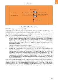
Start net data rate increase
RA-USNRM
Continue SNR margin increase Continue net data rate increase
RA-USNRM -1 dB
Steady state operation
Figure 13-2 – SRA upshift procedure
13.2.1.1.5 Timing and synchronization for SRA
Update of the baseline bit-loading tables at the FTU-O and FTU-R requested via OLR requests types 1, 2 or 3
is synchronized by the associated RMC reply (SRA-R command, see Table 9-15).
Two counts shall be used to maintain synchronization between the configurations imposed by SRA (see
clause 13.2.1.1.1) at the transmitter and the receiver ends:
1) The 4-bit SRA configuration change count (SCCC) is used to identify the particular configuration to
be used. The SRA configuration change count shall be incremented whenever a new configuration
change is initiated by the receiver and wrap around at count 11002, i.e., incrementing from 1100 to
0000, avoiding values 1101 through 1111, which are special values reserved for the TIGA
procedure (see clause 13.2.2.1). In this way, the value of SCCC serves as a unique identifier for the
configuration to be used.
The SCCC shall only be incremented by the receiver.
The SCCC is incremented separately for the NOI and DOI baseline bit loading tables.
2) The 4-bit SRA superframe down count (SFDC) is used to indicate when a new configuration shall
take effect. SFDC shall be decremented in the first RMC symbol of every superframe until reaching
the value zero, which indicates the activation time of the new configuration. The decremented
value shall be repeated in all subsequent RMC symbols of the respective superframe. The d_SRA
scaling factor and new bi, gi, BD and BDR settings shall take effect at the RMC symbol of the first
logical frame of the superframe for which the expected SFDC is 0. The new DTU setting (KFEC, RFEC,
Q) shall take effect at the first DTU following the application of the new bi. Figure 13-3 depicts the
timing of the SRA transition.
The FTU that sends the RMC SRA-R command shall monitor the acknowledgement to this RMC command as
received from the far end via the RMC (RMC ACK bit, see Table 9-5 and Table 9-8). If none of the RMC
messages carrying the SRA-R command was acknowledged, upon reaching SFDC=0, the FTU shall continue
transmitting the same SRA-R command using SFDC=0 until the SRA-R command is acknowledged for the
first time. After acknowledgement is received, the FTU shall consider the procedure complete.
963