
Page 975 - 5G Basics - Core Network Aspects
P. 975
Transport aspects 2
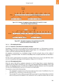
DTU size
increase
0 1 2 3 4 5 6 7 8
DTUs 0 1 2 3 4 Rtx-0 Idl Rtx-1 Idl 5 6
H-0 P-0 ECS H-0 P-0 Idle ECS
Figure 13-4 – Example of mapping of retransmitted DTU 0 and DTU 1 of old
DTU size into a larger new DTU size.
DTU size
decrease
delay_max
0 1 2 3 4 5 6 7 8 9 10
DTUs 0 1 Idl 2 Idl Rtx-0 3 Idl Rtx-1 4 5 6 7 8
H-1 P-1 Idle ECS H-1 P-1 ECS
Figure 13-5 – Example of mapping of retransmitted and new DTU
during the transition time of delay_max.
13.2.1.2 Bit swapping procedure
13.2.1.2.1 Parameters controlled by bit swapping procedure
Bitswapping in downstream may be implemented using OLR request type 1 or 2. Bitswapping in upstream
without change in gi may be implemented using OLR request type 1 or 2. Bitswapping in upstream with
change in gi shall be implemented using OLR request type 2.
Bit swapping is accomplished by a coordinated change to the bits and gain values on the number of
subcarriers in the baseline table. The details on formatting of bits and gains parameters are described in
Table 13-3.
Both the receiver and transmitter shall support any change of the bi and gi values, provided these values
are within the specified valid range and the constraints in clause 13.2.1.2.3 are met.
13.2.1.2.2 Bit swapping procedure
When the value of the SNR on particular subcarriers in the FTU drops below a vendor discretionary
threshold, while the SNRM is still above the value of the downshift SNR margin (RA-DSNRM), the FTU shall
initiate a bit swapping procedure. The SNR and the SNRM shall both be calculated under the assumption
that the active bit-loading table is identical to the baseline bit-loading table.
The procedure comprises the following steps:
– The initiating FTU computes the set of bi and gi values (or only bi values if modification of gi is not
applicable) that is necessary to resolve the drop of the SNR.
– The initiating FTU sends an OLR command of OLR request type 1 or type 2 (depending on whether
both bi and gi need to be modified or the modification is for bi only) that includes the new values
965