
Page 979 - 5G Basics - Core Network Aspects
P. 979
Transport aspects 2
2) Upon reception of the L2TSA request command, the FTU-R shall reply by sending L2TSA response
(response to OLR request type 5, see Table 11-19). The response may confirm (acknowledge) the
L2TSA request or reject it (see Table 11-19).
3) Upon reception of the L2TSA acknowledgement, the FTU-O shall transmit the L2TSA-R RMC
command (see Table 9-17.2) indicating to the FTU-R at which superframe count L2TSA shall be
implemented. If the FTU-O doesn't receive the L2TSA confirmation within the timeout specified in
Table 11-2 or receives a reject, it may repeat the L2TSA request.
4) At the superframe whose index is indicated in L2TSA-R, both FTUs shall change the RMC schedule
to the one indicated in the L2TSA command for each transmission direction.
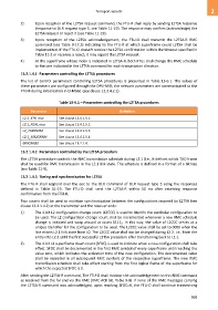
13.2.1.4.1 Parameters controlling the L2TSA procedures
The list of control parameters controlling L2TSA procedures is presented in Table 13-6.1. The values of
these parameters are configured through the DPU-MIB; the relevant parameters are communicated to the
FTU-R during initialization in O-MSG1 (see clause 12.3.4.2.1).
Table 13-6.1 – Parameters controlling the L2TSA procedures
Parameter Definition
L2.1_ETR_min See clause 13.4.1.5.1.
L2.1_NDR_max See clause 13.4.1.5.2.
L2_TARSNRM See clause 13.4.1.5.3.
L2.1_MAXSNRM See clause 13.4.1.5.4.
MINSNRM See clause 13.2.1.4.
13.2.1.4.2 Parameters controlled by the L2TSA procedure
The L2TSA procedure controls the RMC transmission schedule during L2.1 (i.e., it defines which TDD frame
shall be used for RMC transmission in the L2.1 link state. The schedule is defined in a format of a bitmap
(see Table 11-9).
13.2.1.4.3 Timing and synchronization for L2TSA
The FTU-R shall respond over the eoc to the OLR command of OLR request type 5 using the responses
defined in Table 11-19. The FTU-O shall send the L2TSA-R within 50 ms after receiving response
confirmation from the FTU-R.
Two counts shall be used to maintain synchronization between the configurations imposed by L2TSA (see
clause 13.2.1.4.2) at the transmitter and the receiver ends:
1) The 4-bit L2 configuration change count (L2CCC) is used to identify the particular configuration to
be used. The L2 configuration change count shall be incremented whenever a new RMC schedule
change is initiated and wrap around at count 11112. In this way, the value of L2CCC serves as a
unique identifier for the configuration to be used. The L2CCC value shall be set to 0000 when the
line enters L2.1 link state from L0. The L2CCC value shall not be changed during L2.2, i.e., from the
entry into L2.2 until the first successful L2TSA procedure after transitioning back to L2.1.
2) The 4-bit L2 superframe down count (SFDC) is used to indicate when a new configuration shall take
effect. SFDC shall be decremented in the first RMC symbol of every superframe until reaching the
value zero, which indicates the activation time of the new configuration. The decremented value
shall be repeated in all subsequent RMC symbols of the respective superframe. The new RMC
transmission schedule shall take effect starting from the first logical frame of the superframe for
which the expected SFDC is 0.
After sending the L2TSA-R command, The FTU-O shall monitor the acknowledgement to this RMC command
as received from the far end via the RMC (RMC ACK bit, Table 9-8). If none of the RMC messages carrying
the L2TSA-R command was acknowledged, upon reaching SFDC=0, the FTU-O shall continue transmitting
969