
Page 937 - 5G Basics - Core Network Aspects
P. 937
Transport aspects 2
the first sds symbol positions of each downstream logical frame (i.e., O-P-SYNCHRO 1-1 transmission shall
start at the symbol with index 0 of the first downstream logical frame in the superframe); all other
initialization symbols shall be quiet. During transmission of the O-P-SYNCHRO 1-1 signal, the SOC shall be
inactive.
The sync symbols shall be generated and modulated by probe sequences as described in clause 10.2.2.1.
The elements of the probe sequence carried by sync symbols of the O-P-SYNCHRO 1-1 signal shall continue
the probe sequence transmitted during the CHANNEL DISCOVERY 1-1 stage with no interruption.
The symbols of the O-P-SYNCHRO 1-1 signal shall use all subcarriers from the SUPPORTEDCARRIERSds set
modulated as defined in clause 10.2.2.2. The quadrant scrambler shall be in reset mode. The IDS shall not
be applied.
The first sds symbol positions of the downstream logical frames of the O-P-SYNCHRO 1-1 signal shall carry:
– inverted symbols containing SOC IDLE (see clause 12.2.3 for the equivalent definition when the
SOC is in the active state) with robust bit mapping in the first 3 logical frames,
– Symbols containing SOC IDLE with robust bit mapping in the 4th and 5th logical frames, and
– inverted symbols containing SOC IDLE with robust bit mapping in the rest of the logical frames.
The transmit PSD of the O-P-SYNCHRO 1-1 signal shall be equal to CDPSDds.
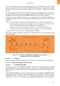
Figure 12-10.1 provides a reference timing diagram of a superframe for construction and placement of each
O-P-SYNCHRO signal.
Duration and placement of an O-P-SYNCHRO signal
t h
First DS logical M SF DS logical
frame in a frame in a
DS sync superframe superframe
symbol
S ds S ds
. . .
. . .
TDD frame 0 TDD frame 1 TDD frame 2 TDD frame 3 TDD frame 4 TDD frame 5 TDD frame M–1 TDD frame M SP
(sync frame)
0 T F 2T F 3T F 4T F 5T F 6T F (M – 1)T F M T F
SF
SF
Beginning of O-P-SYNCHRO
(symbol with index 0)
Superframe: T = M × T F
SF
SF
G.9701(14)-Cor.1(15)_F12-10.1
Figure 12-10.1 – Reference timing diagram of a superframe for construction
and placement of an O-P-SYNCHRO signal.
12.3.3.3.3.3 R-P-QUIET 1
During the CHANNEL-DISCOVERY 1-1 stage the FTU-R shall continue transmission of the R-P-QUIET 1 signal.
12.3.3.3.4 Signals during CHANNEL DISCOVERY 1 stage
12.3.3.3.4.1 O-P-CHANNEL-DISCOVERY 1
During transmission of the O-P-CHANNEL-DISCOVERY 1 signal, the FTU-O communicates to the FTU-R all
necessary information to start upstream transmission. The FTU-R also uses the O-P-CHANNEL-DISCOVERY 1
signal to obtain more accurate symbol timing, train the FEQ and align superframe count between FTU-O
and FTU-R.
The O-P-CHANNEL-DISCOVERY 1 signal shall consist of downstream sync symbols and initialization symbols.
Sync symbols shall be transmitted at each downstream sync symbol position. SOC symbols shall be
transmitted at the first sds symbol positions of each downstream logical frame; all other initialization
symbols shall be quiet. The sync symbols shall be generated and modulated by probe sequences as
927