
Page 911 - 5G Basics - Core Network Aspects
P. 911
Transport aspects 2
If the ITU-T G.994.1 procedures select this Recommendation as the mode of operation, the FTU-R shall
continue with the initialization at the completion of the ITU-T G.994.1 handshake phase, as defined in
clause 12.3.3 and clause 12.3.4.
12.3.2.2.1 CLR messages
An FTU-R indicates its ITU-T G.9701 capabilities in an ITU-T G.994.1 CLR message by setting to ONE the ITU-
T G.9701 SPar(1) bit as defined in Table 11.0.4 of [ITU-T G.994.1]. The NPar(2) (Table 11.69 of
[ITU-T G.994.1]) and SPar(2) (Table 11.70 of [ITU-T G.994.1]) fields corresponding to the ITU-T G.9701
SPar(1) bit are defined in Table 12-14 and Table 12-15, respectively. For each ITU-T G.9701 SPar(2) bit set to
ONE, a corresponding NPar(3) field shall also be present (beginning with Table 11.70.1 in clause 9.4 of
[ITU-T G.994.1]). Table 12-16 shows the definitions and coding for the FTU-R CLR NPar(3) fields.
The FTU-R shall indicate a capability in the CLR message if and only if the capability is supported by the
FTU-R.
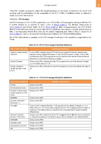
Table 12-14 – FTU-R CLR message NPar(2) bit definitions
ITU-T G.994.1 NPar(2) bit Definition of NPar(2) bit
Support of special probe If set to ZERO, indicates that the FTU-R does not support the use of a special probe
sequence sequence during Channel Discovery 1-1 and Channel Discovery 1 stages. If set to ONE,
indicates that the FTU-R supports the use of a special probe sequence during Channel
Discovery 1-1 and Channel Discovery 1 stages.
Default CE length Always set to ONE. Indicates that the FTU-R supports the use of the default CE length
LCP = m × N/64, where m = 10.
Default number of Always set to ONE. Indicates that the FTU-R supports the use of the default MF value of
symbol periods in TDD 36.
frame
Table 12-15 – FTU-R CLR message SPar(2) bit definitions
ITU-T G.994.1 SPar(2) bit Definition of SPar(2) bit
Profiles Always set to ONE.
DS transmission band Always set to ZERO.
Number of downstream Always set to ZERO.
symbol positions in TDD
frame
RFIBANDS Always set to ZERO.
Duration of Channel Always set to ONE.
Discovery 1-1
CE length If set to ZERO, indicates that the FTU-R supports only the default CE length LCP = m ×
N/64, where m = 10. If set to ONE, indicates that the FTU-R supports valid CE lengths in
addition to the default value, as indicated in the corresponding CE length multiplier
NPar(3) field.
Number of symbol Always set to ONE. Indicates that the FTU-R supports other valid MF values (mandatory
periods in TDD frame or optional) in addition to the default value of 36, as indicated in the related NPar(3).
IARBANDS Always set to ZERO.
Scrambler seed Always set to ZERO.
Special probe sequence Always set to ZERO.
IDS Always set to ZERO.
901