
Page 908 - 5G Basics - Core Network Aspects
P. 908
2 Transport aspects
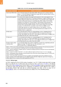
Table 12-10 – FTU-O CL message Npar(3) bit definitions
ITU-T G.994.1 SPar(2) Bit Definition of Npar(3) bits
Downstream RMC offset This 5-bit field indicates the downstream RMC offset expressed in symbols coded as
DRMC,ds –1. The valid range and settings shall comply with the condition defined in clause
10.5.1 with the indicated value of Mds.
Special probe sequence This 140-bit field indicates the length and the elements of the probe sequence to be
used during Channel Discovery 1-1 and Channel Discovery 1 stages of initialization. The
8 MSBs indicate the length of the probe sequence. The remaining 132 bits indicate the
elements of the probe sequence in ascending order of their indices. The first 8 bits
represent first 4 elements, 2 bits per element. The following 124 bits represent the
following 124 elements, 1 bit per element (the LSB of the field indicates the last
element of the sequence (128-th element). If the number of elements in the probe
sequence is less than 128, the unused bits of the 124-bit set shall be set to 0.
The first four elements are coded as follows: 00 and 11 for elements –1 and +1,
respectively, and 01 for element 0. The remaining elements are coded 0 and 1 for
elements -1 and +1, respectively.
CD time out 1 This 3-bit field shall be coded as an unsigned integer n=0 to 7, indicating that the
maximum CD_time_out_1 value supported by the FTU-O equals (n+1) times five
seconds. The maximum CD_time_out_1 value indicated shall be equal to or higher than
the default CD_time_out_1 value of ten seconds.
CD time out 2 This 3-bit field shall be coded as an unsigned integer n=0 to 7, indicating that the
maximum CD_time_out_2 value supported by the FTU-O equals (n+1) times ten
seconds. The maximum CD_time_out_2 value indicated shall be equal to or higher than
the default CD_time_out_2 value of twenty seconds.
Number of SOC symbol This 5-bit field indicates the number of repetitions of each SOC symbol during Channel
repetitions (RS) Discovery 1 stage. The valid values are 0 (no repetitions), 1, and
(k×4-1), where k=1, 2,…floor(sds/4), (Note 4).
NOTE 1 – If FTU-O is part of the vectored group, only the value currently used by the active lines of the vectored group shall be
indicated. In case no vectored group is established, the FTU-O shall indicate all supported values.
NOTE 2 – The list of IAR bands is compliant with [ITU-T G.9700], the mapping of particular IAR bands to the bits of the field shall
be as defined in [ITU-T G.994.1].
NOTE 3 – Except O-P-CHANNEL-DISCOVERY 1-1, for which additional limitations defined in clause 12.3.3.3.3.1 shall apply.
NOTE 4 – The parameter value is set based on internal decision of the VCE and may consider requests from the FTU-Rs from the
previous initializations (Field #5 of R-MSG 1).
NOTE 5 – A list of the profiles supported by the FTU-O is available in the DPU-MIB (through the FTUO_PROFILES inventory
object). Depending on the profiles enabled in the DPU-MIB (through the PROFILES configuration object), the CL message may
indicate support for all or a subset of the profiles supported by the FTU-O.
12.3.2.1.2 MS messages
An FTU-O selecting the ITU-T G.9701 mode of operation in an ITU-T G.994.1 mode select (MS) message
shall set to ONE the ITU-T G.9701 SPar(1) bit as defined in Table 11.0.4 of [ITU-T G.994.1]. The NPar(2)
(Table 11.69 of [ITU-T G.994.1]) and SPar(2) (Table 11.70 of [ITU-T G.994.1]) fields corresponding to this bit
are defined in Table 12-11 and Table 12-12, respectively. For each ITU-T G.9701 SPar(2) bit set to ONE, a
corresponding NPar(3) field shall also be present (beginning with Table 11.70.1 in clause 9.4 of
[ITU-T G.994.1]). Table 12-13 shows the definitions and coding for the FTU-O MS NPar(3) fields.
898