
Page 907 - 5G Basics - Core Network Aspects
P. 907
Transport aspects 2
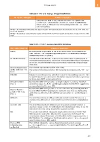
Table 12-9 – FTU-O CL message SPar(2) bit definitions
ITU-T G.994.1 SPar(2) bit Definition of Spar(2) bit
twenty seconds. If set to ONE, indicates that the FTU-O supports valid
CD_time_out_1 values and valid CD_time_out_2 values in addition to the
default values, as indicated in the corresponding CD time out 1 and CD time
out 2 NPar(3) fields.
NOTE 1 – The RFI bands and IAR bands shall apply in the same way to both directions of transmission. The list of RFI bands shall
not include IAR bands.
NOTE 2 – The parameter is determined by request from the FTU-R; the FTU-O is capable to implement all values inside the valid
range.
Table 12-10 – FTU-O CL message Npar(3) bit definitions
ITU-T G.994.1 SPar(2) Bit Definition of Npar(3) bits
Profiles Each valid profile is represented by one bit in a field of 6 bits. The valid profiles are:
106a, 106b and 212a. Each profile supported by the FTU-O is indicated by setting its
corresponding bit to ONE (Note 5).
DS transmission band This field shall include the lower frequency (ftr1-DS) and the upper frequency (ftr2-DS) of
the frequency band assigned for transmission in the downstream direction represented
by the start subcarrier index and stop subcarrier index, respectively, using 12 bits per
index value.
Number of downstream This 6-bit field represents the enabled value of Mds.
symbol positions in TDD The number of US symbol positions in TDD frame shall be computed as Mus = MF – Mds –
frame 1.
RFIBANDS Indicates in ascending order the pairs of start subcarrier index and stop subcarrier index
for each RFI band in which the transmit PSD shall be reduced. Each index is represented
by 12 bits. Up to 32 RFI bands may be defined.
CE length multiplier Each bit of this 9-bit field represents a CE length multiplier m, excluding the default
(Note 1) value 10 (see clause 10.4.4). For each CE length multiplier that the FTU-O supports, the
corresponding bit shall be set to ONE.
Each bit of this 6-bit field represents an MF value other than 36; specifically bit 1 shall
Number of symbol be set to ONE if the FTU-O is configured to use the MF value of 23 and shall be set to
periods in TDD frame ZERO otherwise. Other bits in this 6-bit field are reserved by ITU-T and shall be set to
(Note 1)
ZERO.
IARBANDS This 12-bit field indicates by ONE each IAR band in which transmit PSD reduction is
enabled and by ZERO each IAR band in which transmit PSD reduction is disabled (Note
2).
Scrambler seed This 11-bit field indicates the seed to be used for quadrant scrambler initiation, as
described in clause 10.2.2.4. The MSB indicates the initial setting of the d11 bit and the
LSB indicates the initial setting of d1 bit of the quadrant scrambler.
IDS This variable length bit field indicates the length and the elements of the IDS. The 6
MSB indicate the length of the IDS and shall be mapped onto the first octet. The
remaining bits indicate the elements of the IDS, which shall be mapped as specified in
[ITU-T G.994.1]. The valid length of the IDS is 2 and k×4, where k = 1, 2, ... 8. A special
value 0 indicates that no IDS is applied.
Number of DS This 6-bit field indicates the number of downstream data symbols coded as
initialization data sds – 1 in a logical frame to be used during initialization. The valid range of sds is from 4
symbols (sds) to 32 (Note 3).
897