
Page 910 - 5G Basics - Core Network Aspects
P. 910
2 Transport aspects
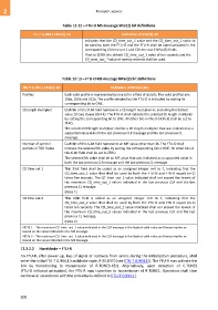
Table 12-12 – FTU-O MS message SPar(2) bit definitions
ITU-T G.994.1 SPar(2) bit Definition of SPar(2) bit
indicates that the CD_time_out_1 value and the CD_time_out_2 value to
be used by both the FTU-O and the FTU-R shall be communicated in the
corresponding CD time out 1 and CD time out 2 NPar(3) fields.
If set to ZERO, the default CD_time_out_1 value of ten seconds and the
CD_time_out_2 value of twenty seconds shall be used.
Table 12-13 – FTU-O MS message NPar(3) bit definitions
ITU-T G.994.1 SPar(2) bit Definition of NPar(3) bits
Profiles Each valid profile is represented by one bit in a field of six bits. The valid profiles are:
106a, 106b and 212a. The profile selected by the FTU-O is indicated by setting its
corresponding bit to ONE.
CE length multiplier Each bit of this 9-bit field represents a CE length multiplier m, excluding the default
value 10 (see clause 10.4.4). The FTU-O shall indicate the selected CE length multiplier
by setting the corresponding bit to ONE. All other bits in this 9-bit field shall be set to
ZERO.
The selected CE length multiplier shall be a CE length multiplier that was indicated as a
supported value in both the last previous CLR message and the last previous CL
message.
Number of symbol Each bit of this 6-bit field represents an MF value other than 36. The FTU-O shall
periods in TDD frame indicate the selected MF value by setting the corresponding bit to ONE. All other bits of
this 6-bit field shall be set to ZERO.
The selected MF value shall be an MF value that was indicated as a supported value in
both the last previous CLR message and the last previous CL message.
CD time out 1 This 3-bit field shall be coded as an unsigned integer n=0 to 7, indicating that the
CD_time_out_1 value that shall be used by both the FTU-O and FTU-R equals (n+1)
times five seconds. The CD_time_out_1 value indicated shall not exceed the lowest of
the maximum CD_time_out_1 values indicated in the last previous CLR and the last
previous CL message.
(Note 1)
CD time out 2 This 3-bit field is coded as an unsigned integer n=0 to 7, indicating that the
CD_time_out_2 value that shall be used by both the FTU-O and FTU-R equals (n+1)
times ten seconds. The CD_time_out_2 value indicated shall not exceed the lowest of
the maximum CD_time_out_2 values indicated in the last previous CLR and the last
previous CL message.
(Note 2)
NOTE 1 – The maximum CD_time_out_1 value indicated in the CLR message is the highest valid value and hence implies no
bound on the value indicated in the MS message.
NOTE 2 – The maximum CD_time_out_2 value indicated in the CLR message is the highest valid value and hence implies no
bound on the value indicated in the MS message.
12.3.2.2 Handshake – FTU-R
An FTU-R, after power-up, loss of signal or recovery from errors during the initialization procedure, shall
enter the initial ITU-T G.994.1 handshake state, R-SILENT0 (see [ITU-T G.994.1]). The FTU-R may activate the
link by transitioning to transmission of R-TONES-REQ. Alternatively, upon detection of C-TONES
(FTU-O initiated activation), the FTU-R may transition to transmission of R-TONE1. Operation shall then
continue in accordance with the procedures defined in [ITU-T G.994.1].
900