
Page 751 - 5G Basics - Core Network Aspects
P. 751
Transport aspects 2
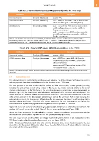
Table 9-17.1 – L2 transition indicator (L2-TRNS) command (sent by the FTU-O only)
Field name Format Description
Command header One byte: [00 aaaaaa] aaaaaa = 1116
L2 transition instant One byte: [0000 aaaa] aaaa = SFDC (see clause 13.2.1.1.5) to the transition
into or out of the given L2 link state (Note 1)
L2 SCCC counts One byte [aaaa bbbb] aaaa = new upstream SCCC count as received in an
L2.1-Entry-Request eoc command or L2.2 Entry-
Request eoc command
bbbb = new downstream SCCC count as received in
an L2.1-Entry-Request eoc command or L2.2 Entry-
Confirm eoc response.
NOTE 1 – For all L2 link state transitions except L2.2 exit, the L2-TRNS shall be repeated in subsequent superframes with a
decrementing value of SFDC, until SFDC reaches the value 0. For L2.2 exit, the L2-TRNS shall be repeated in subsequent active
superframes (see clause 13.4.2.1) with a decrementing value of SFDC, until SFDC reaches the value 0.
Table 9-17.2 – Reply to L2TSA request (L2TSA-R) command (sent by the FTU-O)
Field name Format Description
Command header One byte: [00 aaaaaa] aaaaaa = 1216
L2TSA response data One byte: [bbbb aaaa] aaaa = SFDC (see clause 13.2.1.4.3) to the
implementation of a new RMC transmission
schedule. (Note 1)
bbbb = new L2CCC as received by the L2TSA
request (see clause 11.2.2.5).
NOTE 1 – The transmitter reply shall be repeated in subsequent superframes with a decrementing count until the count reaches
the value 0.
9.7 Acknowledgement
The acknowledgement (ACK) shall be specified per ACK window. The ACK windows shall follow one another
with no gaps and their duration shall be equal to the duration of one TDD-frame.
The time position of the ACK window shall be shifted by "ACK window shift" symbol periods (counting
including the quiet symbol periods falling outside of the Mds and Mus symbol periods), relative to the end of
the last symbol position in the TDD frame in the same direction as the transmission to be acknowledged, as
shown in Figure 9-8 for downstream acknowledgment and Figure 9-9 for upstream acknowledgment. This
means that the ACK window shift for the downstream direction is specified relative to the end of the last
valid symbol position in the downstream direction just before the upstream RMC symbol carrying the
acknowledgements of this downstream ACK window. For the upstream direction, the ACK window shift is
specified relative to the end of the last valid symbol position in the upstream direction just before the
downstream RMC symbol carrying the acknowledgements of this upstream ACK window.
Figure 9-8 shows an example for acknowledging downstream transmissions where the downstream ACK
window shift equals two symbol periods (Figure 9-8a) and seven symbol periods (Figure 9-8b).
Figure 9-9 shows an example for acknowledging upstream transmissions where the upstream ACK window
shift equals one symbol period (Figure 9-9a) and ten symbol periods (Figure 9-9b).
The valid range for ACK window shift is any integer number of symbols from 0 to 20, independent of the
TDD frame length, subject to additional constraints (e.g., see clause 10.5.1).
NOTE – The allowed ACK window shift value for a particular direction is limited by the maximum value for Tack (see
clause 9.8.1). For the selected RMC symbol offsets DRMCus, DRMCds the ACK window shift values within the valid range
also comply with the following conditions:
741