
Page 721 - 5G Basics - Core Network Aspects
P. 721
Transport aspects 2
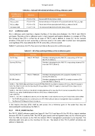
Table 8-6 – ToD and NTR related primitives at the γR reference point
Primitive name
Direction Description
(parameters)
NTR_sc FTU-R → TCE Recovered NTR clock (slave clock).
ToD_sc_value FTU-R → TCE Recovered value of ToD at the NT associated with the ToD_sc_edge.
ToD_sc_edge FTU-R → TCE The instant of time associated with ToD_sc_value at the NT.
ToD slave clock FTU-R → TCE The recovered ToD clock at the NT (slave clock).
8.1.2 α reference point
The α reference point describes a logical interface of the data plane between the TPS-TC and PMS-TC
sub-layers. The data at the α reference point in both transmit and receive directions is a stream of DTUs.
The format of the DTU is unified for all types of TPS-TC and is defined in clause 8.2. In the transmit
direction, DTUs shall be sent across the α reference point in the same order in which user data packets
sourcing these DTUs have entered the TPS-TC across the γ reference point.
Table 8-7 summarizes the DTU flow control primitives that cross the α reference point.
Table 8-7 – DTU flow control primitives at the α reference point
Primitive Direction Description
TX DTU Req PMS-TC TPS-TC Primitive indicating that the PMS-TC is requesting a DTU from
the TPS-TC (Note 1).
Dummy DTU Req Primitive indicating that the PMS-TC is requesting a dummy DTU
from the TPS-TC (Note 1).
Dummy DTU Ind TPS-TC PMS-TC Primitive indicating that the DTU passed to the PMS-TC is a
dummy DTU (Note 3).
RX DTU Enable Primitive indicating that the TPS-TC is ready to receive a DTU
from the PMS-TC. (Note 2).
NOTE 1 – The TX DTU Req primitive is turned off if the PMS-TC is unable to receive a DTU (e.g., the DTU queue is
full). The PMS-TC shall raise the Dummy DTU Req primitive if PMS-TC requires a dummy DTU (see clause 8.2.2)
instead of a data DTU.
NOTE 2 – The TPS-TC shall turn the RX DTU Enable primitive off in case the TPS-TC cannot receive DTUs from the
PMS-TC, e.g., when the RX Enable primitive is off at the γO reference point
(see Table 8-1).
NOTE 3 – The TPS-TC shall send a dummy DTU to the PMS-TC and raise the Dummy DTU Ind primitive when either:
– The TX DTU Req primitive is turned on but no DTU filled with user data or management data is available, or
– The Dummy DTU Req primitive is turned on.
In the receive direction, DTUs shall be sent across the α reference point in the order that they are
recovered (and re-ordered) by the PMS-TC.
8.1.3 TPS-TC_MGMT interface
The TPS-TC_MGMT reference point (see Figure 8-1 for FTU-O and Figure 8-2 for FTU-R) is a logical interface
between the TPS-TC and the FME. The TPS-TC gets control and management data via this reference point
from the FME and returns to the FME the relevant TPS-TC management parameters to be reported. This
reference point also acts as the interface for the eoc. The details of the TPS-TC_MGMT primitives are
defined in Table 8-8.
711