
Page 720 - 5G Basics - Core Network Aspects
P. 720
2 Transport aspects
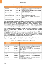
Table 8-4 – DRA related primitives at the γR reference point
Primitive name (parameters) Direction Description
DRRus.request FTU-R → L2+ FTU-R request for an upstream dynamic resource report from
the L2+ functionality in the NT.
DRRus.confirm (DRRus) L2+ → FTU-R Upstream dynamic resource report from the L2+ functionality
in the NT sent to the FTU-R.
DRRus.indicate (NDRR, NRM) FTU-R → L2+ Indicates the values of NDRR and NRM.
DRR.config.request (DRRdata) FTU-R → L2+ The DRR configuration request data.
DRR.config.confirm (DRRdata) L2+ → FTU-R The DRR configuration confirmation data.
Indicates whether or not the FTU-R is operating on reserve
Battery operation (BAT) PSE → FTU-R
batteries.
Indication of the current link state: L0, L2.1N, L2.1B, L2.2 or
LinkState.indicate (LinkState) FTU-R → ME
L3 (see clause 12.1.1.1).
Upon configuration of the NDRR and NRM values using the procedure defined in clause 11.2.2.17, the FTU-R
shall indicate the configured values for NDRR and NRM to the L2+ function through the DRRus.indicate
primitive. The FTU-R shall generate a DRRus.request primitive every NDRR logical frame periods. If NDRR = 0,
the FTU-R shall not generate DRRus.request primitives. The latency in the L2+ functionality between
receiving a DRRus.request primitive and generating the DRRus.confirm primitive (including the upstream
dynamic resource report (DRRus) of NRM bytes length) shall be constant and shall be no greater than one
logical frame period.
If the FTU-R receives a DRRus.confirm primitive during the upstream logical frame with CNTLF,us = N, the
FTU-R shall transmit the DRRus in the RMC no later than during the upstream logical frame with
CNTLF,us = N + 2.
If the FTU-R receives DRR configuration request data through the procedure defined in clause 11.2.2.17,
the FTU-R shall generate a DRRus.config.request primitive to pass the DRR configuration request data to
the L2+ function. Upon receiving a DRRus.config.confirm primitive from the L2+ function, the FTU-R shall
send an acknowledgment to the FTU-O with the DRR configuration confirmation data. The DRR
configuration request/confirm data are transported transparently via the FTU-R.
The NTR and ToD related primitives at the γ reference point (see clauses 8.4 and 8.5 respectively, and see
Figure 8-11) are presented in Table 8-5 for FTU-O and in Table 8-6 for the FTU-R. The primitives also
indicate whether ToD and NTR are enabled and the synchronization option to be used.
Table 8-5 – ToD and NTR related primitives at the γO reference point
Primitive name Direction Description
(parameters)
NTR_mc TCE → FTU-O The 8-kHz NTR clock sourced by the DP (master NTR clock).
NTR_FS_enbl TCE → FTU-O Indicates whether NTR frequency synchronization is enabled or
not. This primitive is set at initialization.
ToD_mc_value TCE → FTU-O The value of ToD sourced by the TCE at the DPU associated with
the ToD_mc_edge.
ToD_mc_edge TCE → FTU-O The instant of time associated with ToD_mc_value sourced by the
TCE at the DPU.
ToD_mc TCE → FTU-O The ToD master clock, multiple of 8 kHz sourced by the TCE at the
DPU.
ToD_enbl TCE → FTU-O Indicates whether ToD is enabled or not. This primitive is set at
initialization.
ToD_FS_enbl TCE → FTU-O Indicates whether ToD frequency synchronization is enabled or
not. This primitive is set at initialization.
710