
Page 717 - 5G Basics - Core Network Aspects
P. 717
Transport aspects 2
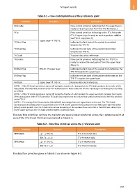
Table 8-1 – Flow control primitives at the γ reference point
Primitive Direction Description
RX Enable Flow control primitive indicating that the upper layer is
ready to receive packets from the TPS-TC (Note 1).
FCus Flow control primitive indicating to the FTU-R that the
FTU-O upper layer is ready to receive packets; valid at
the FTU-O only (Note 3)
Upper layer TPS-TC
TX Start Flag Indicates the first byte of the packet transmitted
towards the TPS-TC.
TX Stop Flag Indicates the last byte of the packet transmitted
towards the TPS-TC.
TX Clock Transmit data clock reference.
TX Enable Flow control primitive indicating that the TPS-TC is
ready to receive the next packet from the upper layer
(Note 2).
RX Start Flag TPS-TC Upper layer Indicates the first byte of the packet transmitted by the
TPS-TC towards the upper layer.
RX Stop Flag Indicates the last byte of the packet transmitted by the
TPS-TC towards the upper layer.
RX Clock Upper layer TPS-TC Receive data clock reference.
NOTE 1 – If the RX Enable primitive is turned off during the transfer of a data packet, the FTU shall complete the transfer of this
data packet. The RX Enable primitive at the FTU-R shall be set to RXon unless the FTU-R is operating in a bonded group according
to G.998.2.
NOTE 2 – If the TX Enable primitive is turned off during the transfer of a data packet, the upper layer shall complete the transfer
of this data packet. At the FTU-R, primitive TX Enable also implements the remote flow control determined by the FCus primitive
at the FTU-O.
NOTE 3 – The setting of the FCus primitive (RXon/RXoff) may change from one logical frame to the next. The FTU-O shall
communicate the setting of the FCus primitive to the FTU-R via the upstream flow control bit in the RMC (see Table 9-5) within
(M F+2) symbol periods. The FTU-R shall communicate the setting of the upstream flow control bit in the RMC (see Table 9-5) to
the NT upper layers via the TX Enable primitive within 2 symbol periods.
The data flow primitives defining the transmit and receive data transferred across the reference point at
each of the FTU-O and FTU-R are summarized in Table 8-2.
Table 8-2 – Data flow primitives across the reference point
Primitive Direction Description
STREAMds L2+ TPS-TC FTU-O transmit data
TPS-TC L2+ FTU-R receive data
STREAMus L2+ TPS-TC FTU-O receive data
TPS-TC L2+ FTU-R transmit data
The data flow primitives given in Table 8-2 are shown in Figure 8-3.
707