
Page 606 - 5G Basics - Core Network Aspects
P. 606
2 Transport aspects
Digitized downlink signal Analog downlink signal Analog downlink signal
Downlink
payload data D/A Analog RoF
(digital baseband) converter Fibre-optic
Uplink Digital modulator/ demodulator Frequency converter Optical transceiver link Optical transceiver Frequency converter RF-band BEP/FEP To/from wireless terminal
payload data A/D
(digital baseband) converter
Analog optical
Digitized uplink signal Analog uplink signal interfaces Analog uplink signal
Network side Antenna side
Analog downlink signal Digitized downlink signal Downlink payload data
From/to remote antenna RF signal EP EP/B RF-band F Frequency converter converter Digital modulator/ demodulator (digital baseband)
Downlink
A/D
Uplink payload data
D/A
Uplink
(digital baseband)
converter
RF signal
Analog uplink signal Digitized uplink signal
Wireless terminal
a)
Digitized downlink signal Digitized downlink signal Analog downlink signal
Downlink
payload data Digital RoF D/A
(digital baseband) Fibre-optic converter
Uplink Digital modulator/ demodulator L2 processor Optical transceiver link Optical transceiver L2 processor Frequency converter RF-band BEP/FEP T o/from wireless terminal
payload data A/D
(digital baseband) converter
Digital optical
interfaces
Digitized uplink signal Digitized uplink signal Analog uplink signal
Network side Antenna side
Analog downlink signal Digitized downlink signal Downlink payload data
From/to remote antenna RF signal EP EP/B RF-band F Frequency converter converter Digital modulator/ demodulator (digital baseband)
Downlink
A/D
Uplink payload data
D/A
Uplink
(digital baseband)
converter
RF signal
Analog uplink signal Digitized uplink signal
Wireless terminal
b) G Suppl.55(15)_F 7-11
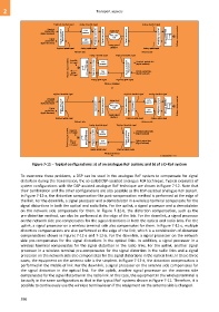
Figure 7-11 – Typical configurations: a) of an analogue RoF system; and b) of a D-RoF system
To overcome these problems, a DSP can be used in the analogue RoF system to compensate for signal
distortion during the transmission, the so-called DSP-assisted analogue RoF technique. Typical examples of
system configurations with the DSP-assisted analogue RoF technique are shown in Figure 7-12. Note that
their combination and the other configurations are also possible as the DSP-assisted analogue RoF system.
In Figure 7-12-a, the distortion compensation-like post-compensation method is performed at the edge of
the link. For the downlink, a signal processor and a demodulator in a wireless terminal compensate for the
signal distortions in both the optical and radio links. For the uplink, a signal processor and a demodulator
on the network side compensate for them. In Figure 7-12-b, the distortion compensation, such as the
pre-distortion method, can also be performed at the edge of the link. For the downlink, a signal processor
on the network side pre-compensates for the signal distortions in both the optical and radio links. For the
uplink, a signal processor on a wireless terminal side also compensates for them. In Figure 7-12-c, multiple
distortion compensations are also performed at the edge of the link, which is a combination of distortion
compensations shown in Figures 7-12-a and 7-12-b. For the downlink, a signal processor on the network
side pre-compensates for the signal distortions in the optical links. In addition, a signal processor in a
wireless terminal compensates for the signal distortion in the radio links. For the uplink, another signal
processor in a wireless terminal pre-compensates for the signal distortion in the radio links and a signal
processor on the network side also compensates for the signal distortions in the optical links. In these three
cases, the equipment on the antenna side is the simplest. In Figure 7-12-d, the distortion compensation is
performed in the middle of link. For the downlink, a signal processor on the antenna side compensates for
the signal distortion in the optical link. For the uplink, another signal processor on the antenna side
compensates for the signal distortion in the radio link. In this case, the equipment in the wireless terminal is
basically in the same configuration as that in the typical RoF systems shown in Figure 7-11. Therefore, it is
possible to continuously use the wireless terminal even if the equipment on the antenna side is changed.
596