
Page 605 - 5G Basics - Core Network Aspects
P. 605
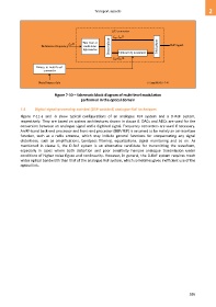
Transport aspects                                              2


                                                               E/O converter
                                                               f – f /2
                                                                   ele
                                                                opt
                                       f /2    Two-tone or
                                       ele
                        Reference frequency    multi-tone    Demultiplexer              Multiplexer  RoF signal
                                               light source        Optical I/Q modulator
                                                               f + f /2
                                                                opt
                                                                   ele
                     Binary-to-multi-level
                         converter


                      Serial binary data                                          G Suppl.55(15)_F7-10


                               Figure 7-10 – Schematic block diagram of multi-level modulation
                                              performed in the optical domain

            7.4     Digital-signal-processing-assisted (DSP-assisted) analogue RoF techniques
            Figure  7-11-a  and  -b  show  typical  configurations  of  an  analogue  RoF  system  and  a  D-RoF  system,
            respectively. They are based on system architectures shown in clause 6. DACs and ADCs are used for the
            conversion between an analogue signal and a digitized signal. Frequency converters are used if necessary.
            An RF-band back-end processor and front-end processor (BEP/FEP) is assumed to be mainly an air-interface
            function,  such  as  a  radio  antenna,  which  may  include  general  functions  for  compensating  any  signal
            distortions,  such  as  amplifications,  bandpass  filtering,  equalizations,  signal  monitoring  and  so  on.  As
            mentioned  in  clause  5,  the  D-RoF  system  is  an  alternative  candidate  for  transmitting  the  waveform,
            especially  in  cases  where  both  distortion  and  poor  sensitivity  hamper  analogue  transmission  under
            conditions of higher noise figure and nonlinearity. However, in general, the D-RoF system requires much
            wider optical bandwidth than that of the analogue RoF system, which sometimes gives inefficient use of the
            optical link.


                                                                                                         595