
Page 1181 - 5G Basics - Core Network Aspects
P. 1181
Transport aspects 2
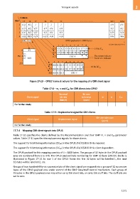
Figure 17-13 OPU2 frame structure for the mapping of a CBR client signal
Table 17-8 – m, n and CnD for CBR clients into OPU2
Nominal Bit rate
Client signal bit rate tolerance m n CnD
(kbit/s) (ppm)
For further study
Table 17-9 – Replacement signal for CBR clients
Bit-rate tolerance
Client signal Replacement signal
(ppm)
For further study
17.7.4 Mapping CBR client signals into OPU3
Table 17-10 specifies the clients defined by this Recommendation and their GMP m, n and CnD parameter
values. Table 17-11 specifies the replacement signals for those clients.
The support for 8-bit timing information (C8D) in the OPU3 JC4/JC5/JC6 OH is required.
The support for 1-bit timing information (C1D) in the OPU3 JC4/JC5/JC6 OH is client dependent.
The OPU3 payload for this mapping consists of 4 3808 bytes. The groups of 32 bytes in the OPU3 payload
area are numbered from 1 to 476. The OPU3 payload byte numbering for GMP 32-byte (256-bit) blocks is
illustrated in Figure 17-14. In row 1 of the OPU3 frame the first 32-bytes will be labelled 1, the next
32-bytes will be labelled 2, etc.
Groups of two hundred-fifty-six successive bits of the client signal are mapped into a group of 32 successive
bytes of the OPU3 payload area under control of the GMP data/stuff control mechanism. Each group of
32 bytes in the OPU3 payload area may either carry 256 client bits, or carry 256 stuff bits. The stuff bits are
set to zero.
1171