
Page 1185 - 5G Basics - Core Network Aspects
P. 1185
Transport aspects 2
#17. The last row contains the GFP payload FCS. The flag (F) bit of 513B block #i (i = 0..7) is carried in Flag #i
bit located in the superblock flags field. The remaining 512 bits of each of the eight 513B blocks of a
superblock are carried in 16 rows of the superblock data field; bits of 513B block #0 in the first 16 rows of
the superblock, bits of 513B block #1 in the next 16 rows, etc. Each 513B block contains 'j' (j = 0..8) control
blocks (CB1 to CBj) and '8-j' all-data blocks (DB1..DB8-j) as specified in Annex B. Figure 17-17 presents a
513B block with three control blocks and five all-data blocks. A 513B block may contain zero to eight
control blocks and a superblock may contain thus zero to sixty-four control blocks.
NOTE 1 – The GFP encapsulation stage does not generate GFP-idle frames and therefore the generated GFP stream is
synchronous to the FC-1200 client stream. The adaptation process performs a 50/51 rate compression, so the
resulting GFP stream has a signal bit rate of 50/51 10.51875 Gbit/s ± 100 ppm (i.e., 10 312 500 kbit/s ± 100 ppm).
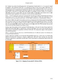
The stream of 8800 octet GFP frames is byte-synchronous mapped into the OPU2e payload by aligning the
byte structure of every GFP frame with the byte structure of the OPU2e payload (see Figure 17-16). Sixty-
four fixed stuff (FS) bytes are added in columns 1905 to 1920 of the OPU2e payload. All the GFP frames
have the same length (8800 octets). The GFP frames are not aligned with the OPU2e payload structure and
may cross the boundary between two OPU2e frames.
During a signal fail condition of the incoming FC-1200 signal (e.g., in the case of a loss of input signal), this
failed incoming FC-1200 signal is replaced by a stream of 66B blocks, with each block carrying two local
fault sequence ordered sets as specified in [b-ANSI INCITS 364]. This replacement signal is then applied at
the transcoding process.
NOTE 2 – Local fault sequence ordered set is /K28.4/D0.0/D0.0/D1.0/. The 66B block contains the following value
SH=10 0x55 00 00 01 00 00 00 01.
During a signal fail condition of the incoming ODU2e/OPU2e signal (e.g., in the case of an ODU2e-AIS,
ODU2e-LCK, ODU2e-OCI condition) a stream of 66B blocks, with each block carrying two local fault
sequence ordered sets as specified in [b-ANSI INCITS 364] is generated as a replacement signal for the lost
FC-1200 signal.
Figure 17-16 Mapping of transcoded FC-1200 into OPU2e
1175