
Page 1179 - 5G Basics - Core Network Aspects
P. 1179
Transport aspects 2
During a signal fail condition of the incoming ODU0 signal (e.g., in the case of an ODU0-AIS, ODU0-LCK,
ODU0-OCI condition), NOS primitive sequence ordered sets as specified in [b-INCITS 470] are generated as
a replacement signal for the lost FC-100 signal.
17.7.1.3 SBCON/ESCON
During a signal fail condition of the incoming SBCON/ESCON signal (e.g., in the case of a loss of input signal),
this failed incoming SBCON/ESCON signal is replaced by an NOS sequence as specified in [b-ANSI INCITS
296].
NOTE – The NOS sequence ordered set is defined as /K28.5/D0.2/.
During a signal fail condition of the incoming ODU0 signal (e.g., in the case of an ODU0-AIS, ODU0-LCK,
ODU0-OCI condition), NOS sequence ordered sets as specified in [b-ANSI INCITS 296] are generated as a
replacement signal for the lost SBCON/ESCON signal.
17.7.2 Mapping a supra-1.238 to sub-2.488 Gbit/s CBR client signal into OPU1
Table 17-6 specifies the clients defined by this Recommendation and their GMP m, n and CnD parameter
values. Table 17-7 specifies the replacement signals for those clients.
The support for 8-bit timing information (C8D) in the OPU1 JC4/JC5/JC6 OH is required.
The support for 1-bit timing information (C1D) in the OPU1 JC4/JC5/JC6 OH is client dependent.
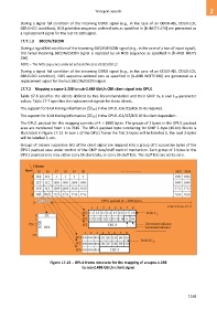
The OPU1 payload for this mapping consists of 4 3808 bytes. The groups of 2 bytes in the OPU1 payload
area are numbered from 1 to 7616. The OPU1 payload byte numbering for GMP 2-byte (16-bit) blocks is
illustrated in Figure 17-12. In row 1 of the OPU1 frame the first 2-bytes will be labelled 1, the next 2-bytes
will be labelled 2, etc.
Groups of sixteen successive bits of the client signal are mapped into a group of 2 successive bytes of the
OPU1 payload area under control of the GMP data/stuff control mechanism. Each group of 2 bytes in the
OPU1 payload area may either carry 16 client bits, or carry 16 stuff bits. The stuff bits are set to zero.
Figure 17-12 OPU1 frame structure for the mapping of a supra-1.238
to sub-2.488 Gbit/s client signal
1169