
Page 1182 - 5G Basics - Core Network Aspects
P. 1182
2 Transport aspects
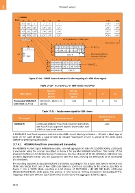
Figure 17-14 OPU3 frame structure for the mapping of a CBR client signal
Table 17-10 – m, n and CnD for CBR clients into OPU3
Nominal Bit rate
Client signal bit rate tolerance m n CnD
(kbit/s) (ppm)
Transcoded 40GBASE-R 1027/1024 64/66 41 100 256 8 Yes
(see clause 17.7.4.1) 250 000
Table 17-11 – Replacement signal for CBR clients
Bit-rate tolerance
Client signal Replacement signal
(ppm)
40GBASE-R Continuous 40GBASE-R local fault sequence ordered sets 100
with four PCS lane alignment markers inserted after each
16383 x 4 sixty-six-bit blocks
A 40GBASE-R local fault sequence ordered set is a 66B control block (sync header = 10) with a block type of
0x4B, an "O" code of 0x00, a value of 0x01 to indicate "local fault" in lane 3, and all of the other octets
(before scrambling) equal to 0x00.
17.7.4.1 40GBASE-R multi-lane processing and transcoding
The 40GBASE-R client signal (64B/66B encoded, nominal aggregate bit-rate of 41 250 000 kbit/s, 100 ppm)
is recovered using the process described in Annex E for parallel 64B/66B interfaces. The lane(s) of the
physical interface are bit-disinterleaved, if necessary, into four streams of 10 312 500 kbit/s. 66B block lock
and lane alignment marker lock are acquired on each PCS lane, allowing the 66B blocks to be de-skewed
and reordered.
The resulting sequence is descrambled and transcoded according to the process described in Annex B into
513B code blocks. Each pair of two 513B code blocks is combined according to the process described in
Annex F into a 1027B block, resulting in a bit stream of 1027/1024 40 000 000 kbit/s 100 ppm
(40,117,187.500 kbit/s 100 ppm). This process is referred to as "timing transparent transcoding (TTT)",
mapping a bit stream which is 1027/1056 times the bit-rate of the aggregate Ethernet signal.
1172