
Page 1176 - 5G Basics - Core Network Aspects
P. 1176
2 Transport aspects
The OPUk overhead for this mapping consists of a:
– payload structure identifier (PSI) including the payload type (PT) as specified in Table 15-9, the
client signal fail (CSF) and 254 bytes plus 7 bits reserved for future international standardization
(RES);
– three justification control (JC1, JC2, JC3) bytes carrying the value of GMP overhead Cm;
– three justification control (JC4, JC5, JC6) bytes carrying the value of GMP overhead CnD and
– one byte reserved for future international standardization (RES).
The JC1, JC2 and JC3 bytes consist of a 14-bit Cm field (bits C1, C2, .., C14), a 1-bit Increment Indicator (II)
field, a 1-bit Decrement Indicator (DI) field and an 8-bit CRC-8 field which contains an error check code over
the JC1, JC2 and JC3 fields.
The JC4, JC5 and JC6 bytes consist of a 10-bit CnD field (bits D1, D2, .., D10), a 5-bit CRC-5 field which
contains an error check code over the bits 4 to 8 in the JC4, JC5 and JC6 fields and nine bits reserved for
future international standardization (RES). The default value of n in CnD is 8. The support for n=1 is client
dependent and specified in the clauses hereafter when required.
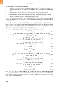
The values of m, Cm,min, Cm,max, n, Cn,min and Cn,max for CBR client into OPUk are as follows:
m , 8 16 , 64 , 256 , 640
(17-1)
CBR _ nom_ client _ bit _ rate Number _ of _ GMP_ blocks _ in _ OPUk
c m, nom (17-2)
OPUk _ nom _ bit _ rate
CBR _1 client _ bit _ rate _ tolerance
c m min, c m, nom (17-3)
1 OPUk _ bit _ rate _ tolerance
CBR _1 client _ bit _ rate _ tolerance
c m max, c m, nom (17-4)
1 OPUk _ bit _ rate _ tolerance
C floor c (17-5)
m , min m , min
C ceiling c (17-6)
m , max m , min
n 1 , 8
(17-7)
CBR _ client _ nom _ bit _ rate Number _ of _ GMP_ blocks _ in _ OPUk
c n, nom (17-8)
OPUk _ nom _ bit _ rate
CBR _1 client _ bit _ rate _ tolerance
c n min, c n, nom (17-9)
1 OPUk _ bit _ rate _ tolerance
CBR _1 client _ bit _ rate _ tolerance
c n max, c n, nom (17-10)
1 OPUk _ bit _ rate _ tolerance
C floor c (17-11)
, n min , n min
C ceiling c (17-12)
, n max , n min
Cm,min, Cn,min, Cm,max and Cn,max values represent the boundaries of client/OPU ppm offset combinations
(i.e., min. client/max. OPU and max. client/min. OPU). In steady state, given instances of client/OPU offset
combinations should not result in generated Cm and Cn values throughout this range but rather should be
within as small a range as possible.
1166