
Page 1183 - 5G Basics - Core Network Aspects
P. 1183
Transport aspects 2
In the mapper, the received Ethernet PCS lane BIP may be compared with the expected Ethernet PCS lane
BIP as a non-intrusive monitor.
The de-mapper will insert a compensated Ethernet PCS lane BIP as described in Annex E. In addition, as
described in Annex E, the combined error mask resulting from the PCS BIP-8 error mask and the OTN BIP-8
error mask may be used as a non-intrusive monitor.
For 40GBASE-R client mapping, 1-bit timing information (C1) is not needed.
The de-mapper will recover from the output of the GMP processor 1027B block lock, and then
trans-decode each 1027B block to sixteen 66B blocks as described in Annex E. Trans-decoded lane
alignment markers are constructed with a compensated BIP-8. The 66B blocks are then re-distributed
round-robin to PCS lanes. If the number of PCS lanes is greater than the number of physical lanes of the
egress interface, the appropriate numbers of PCS lanes are bit-multiplexed onto the physical lanes of the
egress interface.
17.7.5 Mapping CBR client signals into OPU4
Table 17-12 specifies the clients defined by this Recommendation and their GMP m, n and CnD parameter
values. Table 17-13 specifies the replacement signals for those clients.
The support for 8-bit timing information (C8D) in the OPU4 JC4/JC5/JC6 OH is required.
The support for 1-bit timing information (C1D) in the OPU4 JC4/JC5/JC6 OH is client dependent.
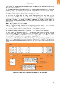
The OPU4 payload for this mapping consists of 4 3800 bytes for client data and 4 8 bytes with fixed
stuff. The groups of 80 bytes in the OPU4 payload area are numbered from 1 to 190. The OPU4 payload
byte numbering for GMP 80-byte (640-bit) blocks is illustrated in Figure 17-15. In row 1 of the OPU4 frame
the first 80-bytes will be labelled 1, the next 80-bytes will be labelled 2, etc.
Groups of six hundred and forty successive bits of the client signal are mapped into a group of 80 successive
bytes of the OPU4 payload area under control of the GMP data/stuff control mechanism. Each group of 80
bytes in the OPU4 payload area may either carry 640 client bits, or carry 640 stuff bits. The stuff bits are set
to zero.
Figure 17-15 OPU4 frame structure for the mapping of a CBR client signal
1173