
Page 1045 - 5G Basics - Core Network Aspects
P. 1045
Transport aspects 2
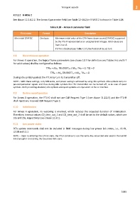
X.7.2.2 R-MSG 2
See clause 12.3.4.2.2. The Annex X parameter field (see Table 12-44.2) in R-MSG 2 is shown in Table X.18.
Table X.18 – Annex X parameter field
Field name Format Description
Min initial DTAFDC One byte Minimum initial value of the DTA frame down count (DTAFDC) supported
by the FTU-R represented as an unsigned 8-bit integer. Valid values are
from 2 to 15.
If DTA is disabled (see Table X.17), the field shall be set to 0.
X.8 Discontinuous operation
For Annex X operation, the logical frame parameters (see clause 10.7 for definition and Tables 9-6 and 9-7
for valid values) shall be configured as follows:
TTRds = Mds, TBUDGETds ≤ Mds, TAds = 0, TIQ = 0
TTRus = Mus,TBUDGETus ≤ Mus, TAus = 0.
During idle symbol periods the FTU may turn its transmitter off.
NOTE – With these settings, only NOI exists, and power saving is achieved by using idle symbols. Idle symbols carry no
pre-compensation signals and thus during idle symbols the FTU transmitter can be turned off, as in case of quiet
symbols. With precoding disabled, idle symbols and quiet symbols are equivalent at the U-interface.
X.9 On-line reconfiguration
For Annex X operation, the FTU-O shall not use OLR Request Type 3 (see clause 11.2.2.5) and the FTU-R
shall reject any received OLR Request Type 3.
X.10 Initialization
For Annex X operation, no vectoring is involved, which reduces the expected duration of initialization.
Therefore, timeout values CD_time_out_1 and CD_time_out_2 shall be set to the default values, which are
10s and 20s, respectively (see clause 12.3.1).
X.11 Low power states
DTA update commands shall not be included in RMC messages during low power link states, i.e., L2.1N,
L2.1B and L2.2.
NOTE – Upon re-entering the L0 link state, the FTUs continue to use the same Mds value that was used in the last L0
link state prior to entering the low power link state.
1035