
Page 1044 - 5G Basics - Core Network Aspects
P. 1044
2 Transport aspects
X.7.1.2.2 MS messages
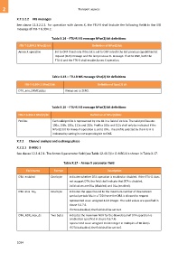
See clause 12.3.2.2.2. For operation with Annex X, the FTU-R shall include the following fields in the MS
message of ITU-T G.994.1:
Table X.14 – FTU-R MS message NPar(2) bit definitions
ITU-T G.994.1 NPar(2) bit Definition of NPar(2) bit
Annex X operation Set to ONE if and only if this bit is set to ONE in both the last previous capabilities list
request (CLR) message and the last previous CL message. If set to ONE, both the
FTU-O and the FTU-R shall enable Annex X operation.
Table X.15 – FTU-R MS message SPar(2) bit definitions
ITU-T G.994.1 SPar(2) bit Definition of Spar(2) bit
DTA_min_DRMCds2us Always set to ZERO.
Table X.16 – FTU-R MS message NPar(3) bit definitions
ITU-T G.994.1 SPar(2) bit Definition of NPar(3) bits
Profiles Each valid profile is represented by one bit in a field of six bits. The valid profiles are:
106a, 106b, 106c, 212a and 212c. Profiles 106c and 212c shall only be indicated if the
NPar(2) bit for Annex X operation is set to ONE. The profile selected by the FTU-R is
indicated by setting its corresponding bit to ONE.
X.7.2 Channel analysis and exchange phase
X.7.2.1 O-MSG 1
See clause 12.3.4.2.1. The Annex X parameter field (see Table 12-41.3) in O-MSG 1 is shown in Table X.17.
Table X.17 – Annex X parameter field
Field name Format Description
DTA_enabled One byte Indicates whether DTA operation is enabled or disabled. If the FTU-O does
not support DTA, the field shall indicate that DTA is disabled.
Valid values are 0016 (disabled) and 0116 (enabled).
DTA_max_Mds One byte Indicates the upper bound to the maximum number of downstream
symbol periods Mds in a TDD frame the DRA is allowed to request
represented as an unsigned 8-bit integer. The valid values are specified in
clause X.6.7.4.
If DTA is disabled, the field shall be set to 0.
DTA_NDR_max_ds Two bytes Indicates the maximum NDR for the downstream if DTA operation is
enabled (as specified in clause X.6.7.4)
represented as an unsigned 16-bit integer in multiples of 96 kbit/s.
If DTA is disabled, the field shall be set to 0.
1034