
Page 1043 - 5G Basics - Core Network Aspects
P. 1043
Transport aspects 2
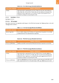
Table X.10 – FTU-O MS message NPar(3) bit definitions
ITU-T G.994.1 SPar(2) bit Definition of NPar(3) bits
Profiles Each valid profile is represented by one bit in a field of six bits. The valid profiles are:
106a, 106b, 106c, 212a and 212c. Profiles 106c and 212c shall only be indicated if the
NPar(2) bit "Annex X operation" is set to ONE. The profile selected by the FTU-O is
indicated by setting its corresponding bit to ONE.
X.7.1.2 Handshake – FTU-R
See clause 12.3.2.2.
X.7.1.2.1 CLR messages
See clause 12.3.2.2.1. For operation with Annex X, the FTU-R shall include the following fields in the CLR
message of ITU-T G.994.1:
Table X.11 – FTU-R CLR message NPar(2) bit definitions
ITU-T G.994.1 NPar(2) bit Definition of NPar(2) bit
Annex X operation If set to ZERO, indicates that FTU-R does not support Annex X operation. If set to ONE,
indicates that the FTU-R supports Annex X operation.
Table X.12 – FTU-R CLR message SPar(2) bit definitions
ITU-T G.994.1 SPar(2) bit Definition of SPar(2) bit
DTA_min_DRMCds2us Shall be set to ONE if and only if the NPar(2) bit for Annex X operation is set to ONE.
Table X.13 – FTU-R CLR message NPar(3) bit definitions
ITU-T G.994.1 SPar(2) bit Definition of NPar(3) bits
Profiles Each valid profile is represented by one bit in a field of 6 bits. The valid profiles are:
106a, 106b, 106c, 212a and 212c. Profiles 106c and 212c shall only be indicated if the
NPar(2) bit "Annex X operation" is set to ONE. Each profile supported by the FTU-R is
indicated by setting its corresponding bit to ONE.
This 3-bit field indicates the minimum number of symbols between the DS RMC and US
DTA_min_DRMCds2us
RMC, supported by the FTU-R. The valid values of DTA_min_DRMCds2us are 4 and 5.
1033