
Page 417 - Kaleidoscope Academic Conference Proceedings 2024
P. 417
Innovation and Digital Transformation for a Sustainable World
Substituting the values of (4), (6), (23) and PL LOS and corresponds to the latency. However, if λ=1, then the final
PL NLOS into (24), and reducing the equations using trigono- optimization function is just the power consumed. Value of
metric calculations, the maximum path loss can be expressed λ between 0 to 1 will depict optimization function as a
as function of latency and power both. The total power of the
UAV is greater than or equal to the sum of hovering and
2
PL max = A + 10 log h + (R c ) 2 + B communication powers, as specified in (30). Additionally, the
h
1+p exp(−q[arctan( R c )−p]) propagation delay/latency is a function of the UAV height and
(25)
coverage radius. Some more details to it are added in the
Here the constants A = η LoS − η NLoS and Appendix.
B = PL NLoS − 20 log d. The value of PL max depends
on the technology being used, receiver sensitivity and the IV. PERFORMANCE EVALUATION
technology for communication used.
This section evaluates the performance of the proposed
The optimal positioning of the UAV would be the one scheme.
that results in covering maximum number of ground users
and satisfactorily meeting their QoS needs. For determining A. Simulation Parameters
the optimal height, h optimal , it is essential to determine the
This section states the parameters for simulations, for the
point satisfying the condition
proposed system. Some of the simulation parameters are
∂R c provided as a range as they are varied to analyze their impact
= 0 (26)
∂h on the optimization result. The parameters are stated in Table
The optimal height will largely depend on the environment 1.
where the UAV is flying. Corresponding to the optimal height,
there will also exist an optimal angle of elevations. The same TABLE I
has been evaluated in [12]. SIMULATION PARAMETERS VALUES
The communication resources like bandwidth, transmitted
Parameters Values
power, etc are assumed to be limited and are shared among all Packet Size (L) 524064 Bits
the users inside the UAV cell. The total bandwidth available Total Bandwidth (B0) 20 MHz
Receiver Temperature (T) 300 K
per UAV coverage area is assumed to be B 0 MHz and total
UAV Power (P 0 ) 50 Watts
power transmitted by a UAV antenna is assumed to be about Transmit Power (P T ) 43 dBm
P T dBm for B 0 MHz of bandwidth. The transmitted signal PLMAX 109–111 dB
2
power for a particular user is calculated accordingly. Total Coverage Area (A T ) 1 –50Km
User Density (ρ) 300–700Km −2
From the equations in the previous section, it can be
deduced that power consumption and latency depend upon h.
At h opt , the latency and power shall also be optimum. This
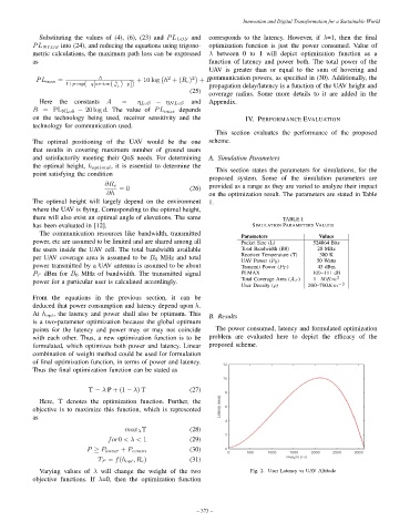
B. Results
is a two-parameter optimization because the global optimum
points for the latency and power may or may not coincide The power consumed, latency and formulated optimization
with each other. Thus, a new optimization function is to be problem are evaluated here to depict the efficacy of the
formulated, which optimizes both power and latency. Linear proposed scheme.
combination of weight method could be used for formulation
of final optimization function, in terms of power and latency.
Thus the final optimization function can be stated as
Υ = λ P + (1 − λ) T (27)
Here, Υ denotes the optimization function. Further, the
objective is to maximize this function, which is represented
as
max λ Υ (28)
for0 < λ < 1 (29)
(30)
P ≥ P hover + P comm
T P = f(h opt , R c ) (31)
Varying values of λ will change the weight of the two Fig. 2. User Latency vs UAV Altitude
objective functions. If λ=0, then the optimization function
– 373 –