
Page 30 - Kaleidoscope Academic Conference Proceedings 2024
P. 30
precoder weights are prone to errors, especially for cell-edge
users. This bottleneck hampers the maximization of network
throughput with MU-MIMO.
In each sector, using 64 antenna ports and DL MU-
MIMO, the base station can serve up to 16 layers, in a paired
MU-MIMO group. Although a theoretical 16-fold increase
in network capacity can be expected compared to a single-
antenna system, practical limitations such as limited antenna
directivity per port, interference from other sectors, and
power division among scheduled layers restrict the number
of users that can be paired and the achievable network
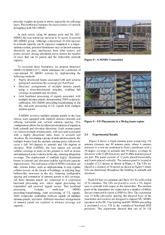
capacity. Figure 8 – S-MIMO Transmitter
To overcome these limitations, we propose Structural
MIMO (S-MIMO) [17], which eliminates the constraints of
conventional 5G MIMO systems by implementing the
following methods:
• Highly directional beams associated with each antenna
port/panel maximizes the coverage per Port/Panel
• Structural arrangements of multiple antenna panels
using a three-dimensional structure, enabling full
coverage in azimuth and elevation.
• Joint baseband processing of signals associated with
multiple antenna panels, incorporating TDD reciprocity
calibration, MU-MIMO precoding/beamforming in the
DL, and joint processing of UL signals from multiple
antenna panels.
S-MIMO involves multiple antenna panels at the base
station, each equipped with multiple antenna elements and
offering horizontal and vertical antenna spacing. This Figure 9 – UE Placements in a 30-deg beam region
configuration allows for the physical orientation of signals in
both azimuth and elevation directions. Each antenna panel
can feature multiple antenna ports, with each port associated
with a highly directional static beam in azimuth and 3.1 Experimental Results
elevation. By structuring a group of such antenna panels, the
multiple beams from the multiple antenna ports collectively Figure 8 shows a single antenna panel comprising 192
cover a full 360 degrees in azimuth and 180 degrees in antenna elements and 48 antenna ports, where 4 antenna
elevation. With S-MIMO, the base station can provide elements in a row are combined to form a port/beam with a
cellular coverage to users on the ground, as well as drones 30-degree coverage in azimuth and 90-degree coverage in
and unmanned aerial vehicles in the sky, ensuring ubiquitous elevation, with 12 dB directivity and 30 dBm transmit power
coverage. The employment of multiple highly directional per port. The panel consists of 12 ports placed horizontally
beams in azimuth and elevation enables significant capacity and 4 ports placed vertically. The antenna panel is located at
improvements. The realization of the S-MIMO structure can a height of 2.5 meters as shown in Figure 8. The UEs are
take various forms, such as implementing it atop regular placed at a distance of 30 meters as shown in Figure 9 where
cellular towers, on the facade of buildings, or utilizing large UEs are distributed throughout the building in azimuth and
balloon-like structures in the sky, featuring configurable elevation.
spacing and orientation of antenna panels to full coverage.
All these antenna panels are connected to a centralized Each UE has two antennas and there 18 UEs with a total
baseband processing unit, where signal processing for of 36 antennas. The UEs are placed to cover a 30- degree
transmitted and received signals occurs. This baseband span in azimuth with respect to the transmitter. The antenna
processing includes multi-user MIMO ports of the transmitter are connected to a number of RRHs
precoding/beamforming, joint processing of UL signals, that are connected to a pool of DSPs by fiber. The experiment
TDD reciprocity calibration between signals of multiple uses 15 KHz sub-carrier spacing, the physical layer of the
antenna panels, and more. Different structural arrangements transmitter and receiver are designed to support MU MIMO
of antenna panels are explored to enhance coverage and operation in the DL. User pairing and MU MIMO precoding
capacity. is performed every TTI in the centralized baseband DSP
processor. The experiment showed that out of 36 UE
– xxvi –