
Page 27 - Kaleidoscope Academic Conference Proceedings 2024
P. 27
decoding with least possible latency. The RS is appended by
RS CP (RS circular pre-fix) of size samples and RS CS
(RS circular suffix) of size that will act as a guard
between RS and data and also enables FFT based channel
estimation.
Figure 1 – OTFDM Symbol Structure.
Further, Additional Reference Signals (ARS) are optionally
transmitted alongside RS and data within an OTFDM
symbol as shown in Figure 1 with samples out of M Figure 3 – Frequency domain spectrum shaping filter.
samples are allocated for ARS transmission. ARS helps in
estimating the residual phase offset arising from the crystal
oscillator frequency drift over time and high speed user Subcarrier 30 60 120 240 Units
channels. Spacing KHz KHz KHz KHz
DFT precoding: As shown in Figure 2, the multiplexed time System 100 200 400 800 MHz
sequence of length M is fed to a M-point DFT module bandwidth
FFT size 4096 4096 4096 4096
Sampling 8.138 4.069 2.0345 1.01725 nS
time
Symbol 33.33 16.67 8.33 4.167 µS
duration
CP 2.344 1.172 0.586 0.293 µS
duration
Figure 2 – OTFDM Transmitter.
TTI
Bandwidth Expansion and Spectrum shaping: The output (symbol + 35.677 17.839 8.919 4.459 µS
of the DFT is appended with a prefix (last ‘v’ samples of the CP
DFT output) and suffix (first ‘v’ samples of the DFT output). duration)
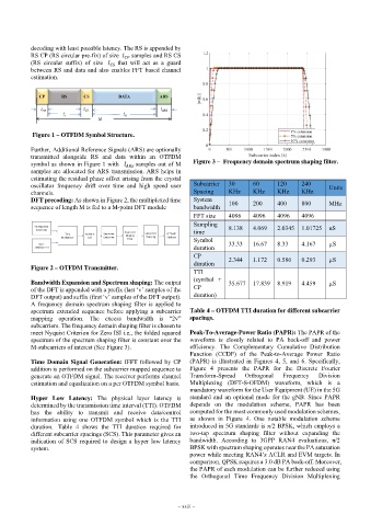
A frequency domain spectrum shaping filter is applied to
spectrum extended sequence before applying a subcarrier Table 4 – OTFDM TTI duration for different subcarrier
mapping operation. The excess bandwidth is “2v” spacings.
subcarriers. The frequency domain shaping filter is chosen to
meet Nyquist Criterion for Zero ISI i.e., the folded squared Peak-To-Average-Power Ratio (PAPR): The PAPR of the
spectrum of the spectrum shaping filter is constant over the waveform is closely related to PA back-off and power
M-subcarriers of interest (See Figure 3). efficiency. The Complementary Cumulative Distribution
Function (CCDF) of the Peak-to-Average Power Ratio
Time Domain Signal Generation: IFFT followed by CP (PAPR) is illustrated in Figures 4, 5, and 6. Specifically,
addition is performed on the subcarrier mapped sequence to Figure 4 presents the PAPR for the Discrete Fourier
generate an OTFDM signal. The receiver performs channel Transform-Sprea Orthogonal Frequency Divisio
estimation and equalization on a per OTFDM symbol basis. Multiplexing (DFT-S-OFDM) waveform, which is a
mandatory waveform for the User Equipment (UE) in the 5G
Hyper Low Latency: The physical layer latency is standard and an optional mode for the gNB. Since PAPR
determined by the transmission time interval (TTI). OTFDM depends on the modulation scheme, PAPR has been
has the ability to transmit and receive data/control computed for the most commonly used modulation schemes,
information using one OTFDM symbol which is the TTI as shown in Figure 4. One notable modulation scheme
duration. Table 4 shows the TTI duration required for introduced in 5G standards is π/2 BPSK, which employs a
different subcarrier spacings (SCS). This parameter gives an two-tap spectrum shaping filter without expanding the
indication of SCS required to design a hyper low latency bandwidth. According to 3GPP RAN4 evaluations, π/2
system. BPSK with spectrum shaping operates near the PA saturation
power while meeting RAN4’s ACLR and EVM targets. In
comparison, QPSK requires a 3.0 dB PA back-off. Moreover,
the PAPR of each modulation can be further reduced using
the Orthogonal Time Frequency Division Multiplexing
– xxiii –