
Page 114 - Kaleidoscope Academic Conference Proceedings 2022
P. 114
2022 ITU Kaleidoscope Academic Conference
the 5G network and synchronizes it to the MEC for I-frame Since the bandwidth resources of different 5G base stations
collision detection. The parameter information includes are not shared, the video streams under different base
device identification, IP address port, channel number, stations collide with I-frames, which will not affect the peak
stream type, I-frame sending start timestamp, I-frame value of the wireless network under a single base station.
sending completion timestamp, code rate, frame rate, Group Therefore, it is necessary to perform packet detection on
of Pictures (GOP) size, etc. front-end equipment. For example, if three devices are under
the same 5G base station, they are grouped according to the
Among them, information such as device identification, IP Cell Global Identity (CGI) of the base station. When I-frame
address port, channel number, and stream type are obtained collision detection is performed, the three devices in the
when the front-end device registers with the video group can be detected. Subsequent processing also only
management platform, and the platform synchronizes to the focuses on within the group.
MEC through the data interface with the MEC; and when the
video streaming starts, Based on information such as device 3.2.2 Network peak scheduling service
identification, IP address and port, the MEC notifies the 5G
network to parse the corresponding data stream, and records Network staggered scheduling refers to calculating the
its I-frame sending start timestamp, I-frame sending weight of each time slot based on time-sharing hashing after
completion timestamp, bit rate, frame rate, GOP size and an I-frame collision occurs, adjusting the I-frame timing of
other information. The second I-frame triggers I-frame the conflicting video device, and forcing its I-frame timing
information collection and reports the collected information to a time slot with a high idle weight, so as to achieve the
to the MEC. collision traffic peak where all front-end video devices are
staggered by I-frame in time.
I-frame collision detection refers to performing time-sharing
hash processing on the collected data. Combined with For example, for a group of front-end video devices, device
parameters such as video terminal grouping, number, GOP, 1 corresponds to timestamp X, hash slot is 1, and the interval
frame rate, etc., it is hashed to the corresponding time slot by is 120ms. I-frame hashing of this group of devices is as
the method of time-sharing hashing. If there are multiple follows in Table 2.
devices in the same time slot, it is regarded as I-frame
collision. Table 2 – I-frame slot hash example
For example, the streaming bit rate is usually configured as Device I-frame Hash slot
FPS=25, GOP=2000ms, and one video frame every 40ms. timestamp
Hash is performed in units of three video frames (120ms) 1 X 1
during hashing, which can fully hash open I-frames and 2 X+80ms 1
achieve a good hashing effect. When there are many video 3 X+500ms 5
front-end devices, the hash interval is adjusted according to
GOP and FPS, and the minimum interval is 1 frame interval It can be seen that the corresponding I-frame time slot hash:
(40ms).
time slot 1 has 2 video front-end devices (I-frame collision),
time slot 5 has 1 video front-end device, every 16 time slots
Assume the timing of video frames of three devices, as (time slot 0-time slot 15). It is regarded as a cycle (the front-
shown in Figure 4. end video equipment sends I-frames regularly), as shown in
Figure 6.
Figure 4 – Video frame timing distribution of multiple Figure 6 – I-frame slot hash example 1
devices
In Figure 6, the minimum value of the time slot is 0, and then
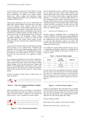
Hash is performed at an interval of 120ms (3 video frames). I-frame time slot of the conflicting device is adjusted to the
The corresponding time slots and collisions are shown in time slot with the minimum value of 0. If there are multiple
Figure 5. I-frames of device 1 and device 3 are hashed to the time slots of 0, then the IPC of the collision I-frame will be
same time slot 1, which is regarded as I-frame collision. adjusted to the slot with the largest idle weight.
Weight calculation method:
Hash value: N ~N (subject to the number of hashes)
0
15
Minimum hash value: N min = min (N ~N )
0
15
Figure 5 – Video I-frame hash distribution
– 68 –