
Page 104 - Kaleidoscope Academic Conference Proceedings 2021
P. 104
2021 ITU Kaleidoscope Academic Conference
loaded. Both the ground plane tracker and the camera grid is placed which continues to expand to detect newer
manager keep getting updated every second. In case there is grids in different places.
a touch recorded, the position of the trackable object is
updated. This is obtained by getting the world coordinates
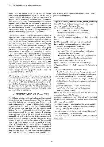
from the screen coordinates and calculating the translation Algorithm 1: Plane_Detection and 3D_Model_Rendering
required. The distance of the translation is the relative Create 3D Assets for home interior models using Maya
distance between the actual position of the trackable object num_total_models = len(tot_models)
and the newly chosen position. An algorithm supported on for ith_model in range(num_total_models):
AR Foundation in the Unity engine is developed for the plane model_parameters = Load vertex coordinate,
detection and rendering of the model (Algorithm -1).
texture coordinate, normal coordinate and the
Virtual content added to a scene needs to know what physical total number of polygons.
objects are in the scene and where exactly they are in the real Export model_parameters to Unity as .obj file by the model
world. This is essential to determine objects that need to be loader
occluded and render the content accurately. The goal of Input the name of the interior models to be rendered
occlusion handling is to preserve the rules of line-of-sight Perform plane detection until motion tracking stops
when creating AR scenes. Whenever the system gets a new Obtain the tracked planes for each frame
frame from the AR camera, it first performs feature point foreach currentPlane in len (newPlanes):
detection. These feature points are then matched to the
previous frame of the camera. The camera motion provides var planeObject = Instantiate a plane visualization
a good idea of where to find the same feature points again in prefab to track the new plane
the new frame which helps with the real-time requirement. Set the transform to origin with identity rotation since
The matching results in an initial camera pose estimation. mesh for prefab is updated in world coordinates
Initially, the match is calculated between two frames and model.transform.position=newVector(0,0,0)
later extended to additional frames. Next, the SLAM Update the state of ARCamera and TrackerManager
algorithm helps to improve the estimate the camera pose in
tracking. The system projects its map into the new camera if Input.touchCount > 0 , find the position of the trackable
frame to search for more key point correspondences. If it is object
certain enough that the key points match, it uses the if Input.Touchphase = = TouchPhase.Began
additional data to refine the camera pose. TouchtoWorldPosition= TrackerManager.GetInstance()
GetWorldPositionFromScreenCoordinate(touchPosition)
AR Hit-testing is a process of resolving if a ray along the else if Input.Touchphase = = TouchPhase.Moved
normal of a screen from a set position intersects with one or currentWorldPosition = TrackerManager.GetInstance()
more objects that are rendered in the application. AR
Raycasting is used to find the first intersection between the GetWorldPositionFromScreenCoordinate(touchPosition)
ray, which has been cast from a set location and along a set Position +=
direction. Algorithm 2 deploys the AR Hit-results to perform (currentWorldPosition - touchToWorldPosition)
dimension scanning and hence it measures the length, width touchToWorldPosition = currentWorldPosition
and height of the home interiors. return the Updated Position
Obtain the pose matrix which describes the position and
4. IMPLEMENTATION AND EVALUATION orientation of a model in 3D space.
The 3D home interior models are implemented by means of poseMatrix=trackable.getPose()*Matrix.Translate(Position)
Autodesk Maya and Substance Designer. The Unity software Use the pose matrix to update the state of 3D transformations
is used for deploying the proposed system. The augmented of the home interior models
reality is implemented by means of AR Foundation which is transform.position = PositionFromMatrix(poseMatrix)
a cross-platform framework in Unity that allows us to build transform.rotate_left =CurrentModel.Rotate(Vector.up*
AR experience once, and then built for Android-based rotateSpeedAmplify * Time.deltaTime)
devices. The Lean Touch module is used for efficient gesture transform.rotate_right=CurrentModel.Rotate(-Vector.up*
recognition across all devices and resolution. It combines
mouse and touch inputs, so that the input code is written only rotateSpeedAmplify * Time.deltaTime
once and it will work perfectly across desktop computers and transform.localScale = PositionFromMatrix(poseMatrix)
mobile devices. It accounts for varying DPI settings, hence return model
it works the same on small and large devices. The real-world
view of the home interior models are stored in a native
gallery of the mobile device via Natcoder API. Seaborn and
Matplotlib libraries in Python are used for heatmap analysis
of touch interaction metrics. The horizontal and vertical
plane detection for the proposed system are shown in Figure
3 where the feature points are identified and eventually a blue
– 42 –