
Page 184 - Kaleidoscope Academic Conference Proceedings 2020
P. 184
2020 ITU Kaleidoscope Academic Conference
satellite. The RSRP series of each UE is generated based
on the channel model in [1] and simulation assumption in
[11]. Secondly, the graph based method in [5] is improved
by setting each satellite in different time slots as different
nodes. The improved method is used to find the best handover
strategies for each UE. Thirdly, the internal relation between
the historical RSRP series and the best handover decision
is extracted by a customized CNN. Since a standard 5G UE
needs to periodically measure the RSRP of the serving cell
and adjacent cells, the UE is able to perform a sub-optimal
handover strategy based on the historical measurements. The
main contributions of this paper are summarized as follows.
• This paper proposes a novel directed graph model for the
handover process. In this model, each beam in different
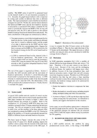
time slots is viewed as different nodes, and the weight Figure 1 – Illustration of the system model
of an edge is determined by the RSRP and the beam
identities of the two corresponding nodes. Suppose the is easy to compute the other 36 beam centers on the plane
beam coverage and the RSRP of a UE is predictable, the according to Figure 1. Then the bore-sight directions of the
best handover strategy for the UE can be found based on 37 beams can be determined. The angles between co-orbital
the model. satellites and adjacent orbits are also calculated to fulfill the
coverage shown in Figure 1.
• A CNN is constructed based on the classical LeNet-5
[12] for handover optimization. The results of the 2.2 Motivation
directed graph model are used to train the parameters
of the CNN. Using the trained CNN, any UE in the LEO In 3GPP simulation assumption Set-1 [11], a satellite of
network is able to perform suboptimal handover based altitude 600 km has beam diameter 50 km and velocity 7.56
on its historical RSRP. km/s. Therefore, a UE can only connect to one beam in
6.6s at most. Because of the noise and the overlapping
of different beams, the handover will happen more often.
The rest of this paper is organized as follows. Section 2 In addition, because of the long propagation time, each
describes the LEO network model and the motivation of handover procedure needs a longer time and will consume
handover optimization. In Section 3, a novel directed graph more time-frequency resource. Therefore in an LEO network
based model is proposed for the handover process. A CNN the handover has time lag and causes a large signaling
structure is constructed and the results of the directed graph overhead. In order to reduce the overhead and improve service
model are used to train the CNN. The effectiveness of the continuity, the handover strategy needs to be optimized for
CNN are numerically evaluated in Section 4. Finally, Section the following targets.
5 concludes this paper.
• Predict the handover decision to compensate the time
lag.
2. BACKGROUND
• Reduce the handover caused by noises, including shadow
2.1 System model
fading, multipath fading and white Gaussian noise.
A typical LEO satellite network consists of several circular • As shown in Figure 2, a UE near the beam edge may have
orbits, and each orbit contains several evenly spaced satellites. a short serving time for some beams. It is beneficial to
This paper considers the scenario in Figure 1 where each identify and suppress the handover in this situation.
hexagon denotes the coverage of a satellite. Refer to the
assumptions [11], [13] used in 3GPP NTN study item, each
satellite is assumed to have 37 beams which form the hexagon
coverage. The UEs are assumed to locate within a hexagon In this paper, an overall handover optimization is obtained in
in initial time, and the satellites in the three adjacent orbits the directed graph model for each UE. The common features
are considered to evaluate the RSRPs on the UEs. During the of the optimized strategies for different UEs are extracted
flight of the satellites, a UE needs to periodically measure the using CNN to fulfill the targets without strong requirements
RSRPs of different beams and make handover decisions. for UE capability.
3. HANDOVER STRATEGY OPTIMIZATION
The beam layout in Figure 1 decides the center of the 37 BASED ON CNN
beams in the UV plane [13]. Briefly speaking, suppose the
satellite is above a plane, then the diameter of the nadir beam In a LEO satellite network, the satellites fly along
on the plane can be computed based on the 3dB angle. It predetermined circular orbits, so the change of the RSRP
– 126 –