
Page 110 - ITU-T Focus Group IMT-2020 Deliverables
P. 110
3 ITU-T Focus Group IMT-2020 Deliverables
R R
R
R R
AN EN IP/MPLS EN AN
Network
R
R
R R
FlexE Conn.
User Data
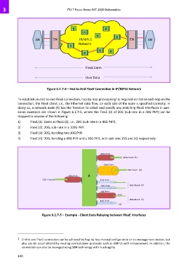
Figure 6.1.7-4 – End-to-End FlexE Connection in IP/MPLS Network
1
To establish an end-to-end FlexE connection, hop-by-hop provisioning is required so that at each hop on the
connection, the FlexE client, i.e., the Ethernet data flow, on each side of the node is specified correctly. In
doing so, a network node (R) has the freedom to select and specify any matching FlexE interfaces in pair.
Some examples are shown in Figure 6.1.7-5, where the FlexE (0) of 20G (sub-rate in a 40G PHY) can be
mapped to anyone of the following:
1) FlexE (1): Same as FlexE (0), i.e., 20G (sub-rate in a 40G PHY).
2) FlexE (2): 20G, sub-rate in a 100G PHY.
3) FlexE (3): 20G, bonding two 10G PHY.
4) FlexE (4): 20G, bonding a 40G PHY and a 10G PHY, with sub-rate 15G and 5G respectively.
40G PHY
20G FlexE (1)
100G PHY
20G FlexE (2)
40G PHY R
20G FlexE(0) 10G PHY
10G PHY 20G FlexE (3)
40G PHY
15G
20G FlexE (4)
10G PHY
5G
Figure 6.1.7-5 – Example - Client Data Relaying between FlexE Interfaces
1 End-to-end FlexE connection can be achieved by hop-by-hop manual configuration or via management station, but
also can be accomplished by existing control plane protocols such as GMPLS with enhancement. In addition, the
connection can also be managed using SDN technology with much agility.
104