
Page 109 - ITU-T Focus Group IMT-2020 Deliverables
P. 109
ITU-T Focus Group IMT-2020 Deliverables 3
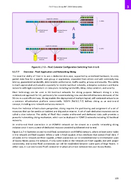
Length 20 sub-calendars
Length 20 n calendars
4 x 100G
A
10G FlexE Channel 25G FlexE Channel
(Client X) (Client Y)
B Length 20 sub-calendars
Length 20 n calendars
4 x 100G
35G FlexE Channel 20G FlexE Channel
(Client X) (Client Y)
Figure 6.1.7-3 – FlexE Calendar Configuration Switching from A to B
6.1.7.7 Overview - FlexE Application and Networking Slicing
The essential ability of FlexE is to use a dedicated data pipe, supported by underlined hardware, to carry
packet data flow for a specific user group or application, separated from others and with extremely low
latency, guaranteed bandwidth, deterministic performance, traffic quality, privacy and security. This ability
is much appreciated and valuable especially for mobile backhaul networks, enterprise customers and home
networks with rigid requirement on data plane including bandwidth, delay, delay variation, and security.
FlexE technology can be used in 5G backhaul networks for slicing purpose. Network slicing is a key
architectural approach for 5G, particularly for accommodating new and diversified business demands of the
5G era in a cost-efficient way. Slicing enables the deployment of multiple logical, self-contained networks on
a common infrastructure platform concurrently. NGMN [Ref.6.1.7-3] defines slicing as an end-to-end
concept, including core network and access network.
From the technical infrastructure perspective, slicing requires the partitioning and assignment of a set of
resources that can be used in an isolated and disjunctive manner. A set of such dedicated resources can be
called a slice instance. The ability of FlexE that creates end-to-end and dedicated data path provides a
powerful networking slicing mechanism, which can be deployed in IP/MPLS networks including 5G backhaul
networks.
An end-to-end FlexE connection in an IP/MPLS network can be viewed as a specific networking slicing
instance since it owns a piece of dedicated resource provided by Ethernet end-to-end.
Figure 6.1.7-4 illustrates an end-to-end FlexE connection in an IP/MPLS network, where at least some nodes
in the network are FlexE-capable. When a node is FlexE-capable, it has interfaces that contain FlexE shim. If
all nodes in the network are FlexE-capable, a FlexE connection can be established end-to-end between pairs
of Access Nodes across the network. If only some nodes in the network are FlexE-capable, but with proper
connectivity, end-to-end FlexE connections can still be established between some pairs of Edge Nodes. In
either case, it is an end-to-end FlexE connection in physical context between two peer Access Nodes.
103