
Page 105 - ITU-T Focus Group IMT-2020 Deliverables
P. 105
ITU-T Focus Group IMT-2020 Deliverables 3
6.1.6 Standardization activities at IETF on SFC
The delivery of end-to-end services often requires to traverse various service functions along a
predetermined path. The term “Service Function Chaining” has emerged to describe the deployment of
composite services that are constructed from one or more service function. Modern networks require to
have the agility and flexibility to dynamically chain functions together based on network or business
requirements—without having to manually reconfigure network components.
By leveraging SDN and NFV techniques, Service Function Chaining allows operator to develop new services
by intelligently chaining multiple functions within the network, as well as to reduce time to market and lower
operational costs for new service deployment.
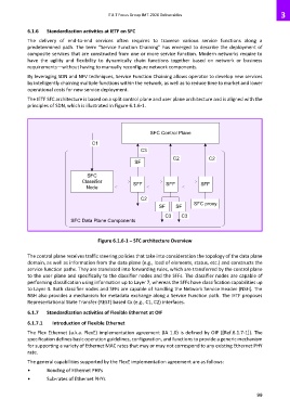
The IETF SFC architecture is based on a split control plane and user plane architecture and is aligned with the
principles of SDN, which is illustrated in Figure 6.1.6-1.
SFC Control Plane
C1
C3
C2 C2
SF
SFC
Classifier SFF SFF SFF
Node
C2
SF SF SFC proxy
C3 C3
SFC Data Plane Components
Figure 6.1.6-1 – SFC architecture Overview
The control plane receives traffic steering policies that take into consideration the topology of the data plane
domain, as well as information from the data plane (e.g., load of elements, status, etc.) and constructs the
service function paths. They are translated into forwarding rules, which are transferred by the control plane
to the user plane and specifically to the classifier nodes and the SFFs. The classifier nodes are capable of
performing classification using information up to Layer 7, whereas the SFFs have classification capabilities up
to Layer 4. Both classifier nodes and SFFs are capable of handling the Network Service Header (NSH). The
NSH also provides a mechanism for metadata exchange along a Service Function path. The IETF proposes
Representational State Transfer (REST) based Cx (e.g., C1, C2) interfaces.
6.1.7 Standardization activities of Flexible Ethernet at OIF
6.1.7.1 Introduction of Flexible Ethernet
The Flex Ethernet (a.k.a. FlexE) implementation agreement (IA 1.0) is defined by OIF ([Ref.6.1.7-1]). The
specification defines basic operation guidelines, configuration, and functions to provide a generic mechanism
for supporting a variety of Ethernet MAC rates that may or may not correspond to any existing Ethernet PHY
rate.
The general capabilities supported by the FlexE implementation agreement are as follows:
• Bonding of Ethernet PHYs
• Sub-rates of Ethernet PHYs
99