
Page 106 - ITU-T Focus Group IMT-2020 Deliverables
P. 106
3 ITU-T Focus Group IMT-2020 Deliverables
• Channelization within a PHY or a group of bonded PHYs
Enhancement of FlexE capability (FlexE2.0 project at OIF) is currently under consideration at OIF, and the
improvement of FlexE 2.0 includes areas in flexibility, granularity, interoperability, and inclusion of Ethernet
200G/400G (currently under development by IEEE).
6.1.7.2 Terms and Definitions
FlexE Flexible Ethernet.
FlexE Group Refers to a group of from 1 to n bonded Ethernet PHYs.
FlexE client An Ethernet flow based on a MAC data rate that may or may not correspond to any
Ethernet PHY rate.
Ethernet PHY Refers to Ethernet physical layer.
FlexE shim Refers to the layer that maps or demaps the FlexE clients carried over a FlexE group.
6.1.7.3 Abbreviations and Acronyms
FlexE Flexible Ethernet
PHY OSI physical layer
PTN Packet-based Transport Network
SDN Software Defined Network
6.1.7.4 Overview of FlexE Data Plane
FlexE technology provides a generic mechanism to support varies of Ethernet MAC rates (e.g., 25G, 50G,
125G, etc.) that do not correspond to any standards based Ethernet PHY rate (e.g., 40G, 100G, etc.). The
Ethernet MAC rate reflects a user or application based data flow, which may be larger or less than that of an
Ethernet PHY. In the former case, FlexE allows that an Ethernet traffic flow, called FlexE client, to be carried
over on more than one and bonded Ethernet PHYs, and in the latter case, to be carried within one Ethernet
PHY (called sub-rating), or a group of bonded Ethernet PHYs (called channelization).
The following sections describe some general concepts and characteristics of FlexE data plane. These
characteristics and related requirements are on FlexE interfaces.
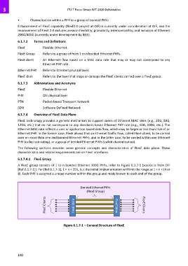
6.1.7.4.1 FlexE Group
A FlexE group consists of 1 to n bonded Ethernet 100G PHYs, refer to Figure 6.1.7-1 (source is from OIF
[Ref.6.1.7-1]). Per [Ref.6.1.7-1], 1 < n < 255, but the initial implementation will limit the range as 1 < n < (4 or
8). Each PHY is assigned a unique number within the group and made known to each end of the group.
Bonded Ethernet PHYs
(FlexE Group)
FlexE Clients Shim FlexE FlexE Shim FlexE Clients
Figure 6.1.7-1 – General Structure of FlexE
100