
Page 108 - ITU-T Focus Group IMT-2020 Deliverables
P. 108
3 ITU-T Focus Group IMT-2020 Deliverables
3) Channelization
FlexE allows several data flows be carried over a single Ethernet PHY or a group of bonded PHYs,
with the MAC rate of each flow be mapped to a FlexE connection. E.g., a data flow at MAC rate 150G
and two other data flows at MAC rate 25G each can be carried over on two bonded Ethernet 100G
PHYs.
6.1.7.5 OAM
Section 7.5.2 of [Ref.6.1.7-1] describes two cases for the FlexE Demux fault handling.
First, if the intra-PHY skew exceeds the skew tolerance of the implementation, the FlexE clients will not be
demapped from the incoming PHYs, and this local fault condition must be communicated to the transmitting
side.
Second, if one or more of the PHYs of the FlexE group has failed (e.g., loss of signal, failure to achieve block
lock or alignment lock, high BER, etc.), this is treated as a local fault condition that must be communicated
to the transmitting side.
In both cases, the receiving side (transmitting side in the above) would receive the fault information as
Remote PHY Fault (RPF), as described in Section 7.3.8 of [Ref.6.1.7-1].
Other OAM aspects for FlexE are elaborated in Appendix FlexE-2.
6.1.7.6 Resizing of FlexE Connection
The bandwidth on an existing FlexE connection, i.e., the Ethernet MAC rates (e.g., 25G, 50G, 125G, etc.)
sometimes need to be increased or decreased based on requirement from customers or applications, and
this is called resizing of FlexE Connection.
As explained in Section 6.1.7.3.4, there are two FlexE calendar configurations available, and so while one is
active, the other one can be (re-)configured with smaller (downsizing) or larger (upsizing) MAC rates followed
by a switch operation so the FlexE connection is now running on the second configuration with a resized MAC
rate.
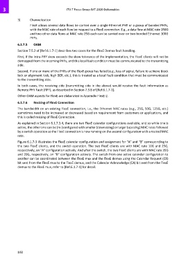
Figure 6.1.7-3 illustrates the FlexE calendar configuration and assignment for “A” and “B” corresponding to
the two FlexE clients, and the switch operation. The two FlexE clients are with MAC rate 10G and 25G,
respectively, on “A” configuration actively. And after the switch, the two FlexE clients are with MAC rate 35G
and 20G, respectively, on “B” configuration actively. The switch from one active calendar configuration to
another can be coordinated between the FlexE mux and the FlexE demux using the Calendar Request (CR)
bit sent from the FlexE mux to the FlexE demux, and the Calendar Acknowledge (CA) bit sent from the FlexE
demux to the FlexE mux, refer to [Ref.6.1.7-1] for detail.
102