
Page 804 - 5G Basics - Core Network Aspects
P. 804
2 Transport aspects
Symbol positions in a logical frame assigned for downstream transmission are indexed from zero to
(Mds –1). Symbol positions assigned for upstream transmission in a logical frame are indexed from zero to
(Mus –1). The indexing for each transmission direction starts from the RMC symbol, whose position has
index zero in both upstream and downstream.
SF
Downstream logical frame N+M SF Downstream logical frame N+M +1 Downstream logical frame N+2×M SF – 1 Downstream logical frameN+2×M SF
D RMCds (first in the superframe P) (second in thesuperframe P) ... (last in the superframe P) (first in the superframe P+1)
Downstream D D ... S R D ... D D RMCus D D ... D R D ... D D D ... D R D ... D D D ... S R D ... D D
transmission
Upstream ...
transmission S D R ... D D D R ... D D D R ... D S D R ... D
M ds M us
Upstream logical frame N 1– Upstream logical frame N Upstream logical frame N+M SF – 1
(last in the superframe P –1) (first in the superframe P) Upstream logical frame N+M SF – 2 (last in the superframe P)
TDD frame 0 (sync frame) TDD frame 1 TDD frame M SF – 1 TDD frame 0 (sync frame)
Superframe P Superframe P+1
S Sync ymbols R RMC ymbols D Data ymbols
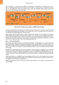
G.9701(14)_F10-27
Figure 10-27 – Example of sync symbol and RMC symbol positions
As shown in Figure 10-27, any logical frame that starts during a TDD frame of a particular superframe shall
be considered belonging to this superframe (even though the end of the last logical frame of a superframe
is transmitted at the beginning of the next superframe).
16
Logical frames shall be counted using a modulo 2 logical frame counter. The transmitter shall increment
the logical frame count (CNTLF) every time a logical frame is sent. The CNTLF values are defined for upstream
(CNTLF-us) and downstream (CNTLF-ds). The CNTLF shall be reset at the transition into showtime: the CNTLF-ds
shall be reset at the first downstream logical frame transmitted at the showtime and the CNTLF-us shall be
reset at the first upstream logical frame transmitted at the showtime.
10.5.2 Data symbol positions
Downstream data symbols shall be transmitted at downstream symbol positions of a logical frame with
indices starting from 1 and determined by the parameters TTRds, TAds and TBUDGETds defined in clause 10.7.
The number of data symbols in a downstream logical frame that does not contain a sync symbol may be up
to Mds–1, and in those that contain sync symbol may be up to Mds–2. Index 0 is assigned to the downstream
RMC symbol.
Upstream data symbols shall be transmitted at upstream symbol positions of a logical frame with indices
starting from one and determined by the parameters TTRus, TAus and TBUDGETus defined in clause 10.7. The
number of data symbols in a upstream logical frame that does not contain a sync symbol may be up to Mus-
1 and in those that contain sync symbol may be up to Mus–2. Index 0 is assigned to the upstream RMC
symbol.
An idle symbol may be transmitted at any data symbol position that is not used by a data symbol using the
rules determined by the selected configuration parameters for discontinuous operation (see clause 10.7).
This applies to both upstream and downstream.
At data symbol positions that are not used by either a data symbol or an idle symbol, a quiet symbol shall
be transmitted.
794