
Page 809 - 5G Basics - Core Network Aspects
P. 809
Transport aspects 2
TDD sync frame (M = 23 symbol s; T F = M F × T seconds) TDD sync frame (M = 23 symbol s; T F = M × T seconds)
F
F
S
S
F
M = 14 Upstream M = 8 M = 14 Upstream M = 8 M = 14 M = 8
ds
us
ds
us
us
ds
Line 1 Downstream rmc d d d d Downstream rmc d d d q Downstream rmc d ...
TTR = 3; TBUDGET = 5; TA = 0; TTR = 3; TBUDGET = 4; TA = 0;
us
us
[B' = 2, B = 2]; us us [B' = 2, B = 1]; us us
Line 2 Downstream rmc d d d d Downstream rmc d d d d Downstream rmc d ...
TTR = 3; TBUDGET = 5; TA = 0; TTR = 3; TBUDGET = 5; TA = 0;
us
us
us
us
us
us
[B' = 2, B = 2]; [B' = 2, B = 2];
Line 3 Downstream d d d rmc d d Downstream d q rmc d d Downstream d d d rmc d ...
TTR = 3; TBUDGET = 5; TA = 3; TTR = 3; TBUDGET = 6; TA = 2;
us
us
us
us
us
us
[B' = 2, B = 1] [B' = 3, B = 3];
Line 4 Downstream d q q rmc d d Downstream d d rmc d d Downstream d q q rmc d ...
TTR = 3; TBUDGET = 5; TA = 3; TTR = 3; TBUDGET = 6; TA = 2;
us
us
us
us
us
us
[B' = 2, B = 2]; [B' = 3, B = 1];
t = 0 DRMC = 3 NOI t = T F DOI NOI DOI
us
Upstream logical frame (T ) containing sync symbol Upstream logical frame (T ) without sync symbol
F
F
G.9701(14)_F10-30
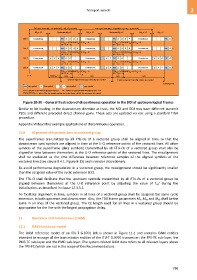
rmc rmc symbol d data symbol = q quiet symbol sync symbol
TTR = duration of the normal operation interval TA = number of quiet symbols immediately after TTR
TBUDGET+TA–1 = index of the last symbol position in a logical frame eligible for carrying a data symbol
Figure 10-30 – General illustration of discontinuous operation in the DOI of upstream logical frames
Similar to bit loading, in the downstream direction at least, the NOI and DOI may have different transmit
PSDs and different precoded direct channel gains. These sets are updated via eoc using a standard TIGA
procedure.
Appendix VI describes example applications of discontinuous operation.
10.8 Alignment of transmissions in vectored group
The superframes transmitted by all FTU-Os of a vectored group shall be aligned in time so that the
downstream sync symbols are aligned in time at the U-O reference points of the vectored lines. All other
symbols of the superframe (data symbols) transmitted by all FTU-Os of a vectored group shall also be
aligned in time between themselves at the U-O reference points of the vectored lines. The misalignment
shall be evaluated as the time difference between reference samples of the aligned symbols of the
vectored lines (see clause 8.4.1, Figure 8-12) and is vendor discretionary.
To avoid performance degradation in a vectored group, the misalignment should be significantly smaller
than the assigned value of the cyclic extension (CE).
The FTU-O shall facilitate that the upstream symbols transmitted by all FTU-Rs of a vectored group be
aligned between themselves at the U-O reference point by adjusting the value of Tg1' during the
initialization, as described in clause 12.3.3.1.
To facilitate alignment in time, symbols in all lines of a vectored group shall be assigned the same cyclic
extension, in both upstream and downstream. Also, the TDD frame parameters MF, Mus and Mds shall be the
same in all lines of the vectored group. The CE length used for all lines in a vectored group should be
appropriate for the line with the largest propagation delay.
11 Operation and maintenance (OAM)
11.1 OAM functional model
The OAM reference model of an ITU-T G.9701 link is shown in Figure 11-1 and contains OAM entities
intended to manage all the transmission entities of the ITU-T G.9701 transceiver: the TPS-TC sub-layer, the
PMS-TC sub-layer and the PMD sub-layer. The system-related OAM data refers to all relevant layers above
the TPS-TC (which are not in the scope of this Recommendation).
799