Page 800 - 5G Basics - Core Network Aspects
P. 800
2 Transport aspects
10.4.3 Inverse discrete Fourier transform (IDFT)
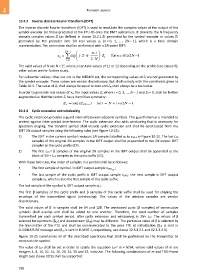
The inverse discrete Fourier transform (IDFT) is used to modulate the complex values at the output of the
symbol encoder (or those precoded at the FTU-O) onto the DMT subcarriers. It converts the N frequency
domain complex values Zi (as defined in clause 10.2.1.5) generated by the symbol encoder or values Zi'
generated by the precoder into 2N real values xn (n = 0, 1, ..., 2N − 1), which is a time domain
representation. The conversion shall be performed with a 2N-point IDFT:
2N 1 n i
x n exp j 2 Z i for n 0 to 2 N 1
i 0 2 N
p
The valid values of N are N = 2 , where p can take values of 11 or 12 depending on the profile (see clause 6);
other values are for further study.
For subcarrier indices i that are not in the MEDLEY set, the corresponding values of Zi are not generated by
the symbol encoder. These values are vendor discretionary, but shall comply with the constraints given in
Table 10-5. The value of Z0 shall always be equal to zero and ZN shall always be a real value.
In order to generate real values of xn, the input values Zi, where i = 0, 1, ..., N − 1 and Z0 = 0, shall be further
augmented so that the vector Zi has a Hermitian symmetry:
Z i conj ( Z 2N i ) for Ni 1 to 2 N 1
10.4.4 Cyclic extension and windowing
The cyclic extension provides a guard interval between adjacent symbols. This guard interval is intended to
protect against inter-symbol interference. The cyclic extension also adds windowing that is necessary for
spectrum shaping. The transmit symbol shall include cyclic extension and shall be constructed from the
IDFT 2N output samples using the following rules (see Figure 10-25):
1) The IDFT in the current symbol i outputs 2N samples labelled x0 to x2N-1 in Figure 10-25. The last LCP
samples of the original 2N samples in the IDFT output shall be prepended to the 2N output IDFT
samples as the cyclic prefix (CP).
2) The first LCS = β samples of the original 2N samples in the IDFT output shall be appended to the
block of 2N + LCP samples as the cyclic suffix (CS).
With these two rules, the order of samples in a symbol shall be as follows:
• The first sample of symbol i is IDFT output sample x2N-L ;
CP
• The last sample of the cyclic prefix is IDFT output sample x2N-1; the next sample is IDFT output
sample x0, which is also the first sample of the cyclic suffix;
The last sample of the symbol is IDFT output sample xβ-1.
The first β samples of the cyclic prefix and β samples of the cyclic suffix shall be used for shaping the
envelope of the transmitted signal (windowing). The values of the window samples are vendor
discretionary.
The valid values of β in samples shall be 64 and 128. The windowed parts (β samples) of consecutive
symbols shall overlap and shall be added to one another. Therefore, the total number of samples
transmitted per each symbol period, after cyclic extension and windowing, is 2N+ LCP. The values of β
selected for upstream (βus) and downstream (βds) may be different. The particular value of β is selected by
the transmitter of the FTU and shall be communicated to the peer FTU at initialization (βds is sent in
O-SIGNATURE message and βus is sent in R-MSG 1, respectively, see clause 12.3.3.2.1 and 12.3.3.2.3).
Figure 10-25 summarizes all of the described operations that shall be performed by the transmitter to
construct the symbol.
The value of LCP shall be set in order to satisfy the equation LCP= m × N/64, where valid values of m are
integers 4, 8, 10, 12, 14, 16, 20, 24, 30 and 33, inclusive. The following combinations of m and TDD frame
length (see clause 10.5) shall be supported:
790

