
Page 803 - 5G Basics - Core Network Aspects
P. 803
Transport aspects 2
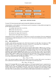
Figure 10-26 – TDD frame structure
The same TDD frame structure shall be used during both initialization and showtime.
During showtime, symbol periods in a TDD frame are used for transmission of data symbols (carrying DTUs)
and the following special symbols:
– Sync symbol: See clauses 10.2.2.1 and 10.6.
– RMC symbol: See clause 10.5.1.
– Pilot symbol: See clauses 10.2.2.3 and 10.4.5.1.
– Idle symbols: See clauses 10.2.1.7 and 10.7.
– Quiet symbols: See clauses 10.2.1.6 and 10.7.
During the initialization, symbol periods in a TDD frame are used for transmission of the sync symbols and
the initialization symbols (see clauses 12.3.3.3 and 12.3.4.3). The format of initialization symbols is defined
in clause 10.2.2.2.
10.5.1 RMC symbol position
An RMC symbol shall be transmitted every TDD frame during the L0 link state. Transmission of RMC
symbols during L2.1 and L2.2 link states is specified in clause 13.4.1.1 and clause 13.4.2.1, respectively.
The format and encoding of RMC symbol are described in clause 9.6.
The position of the downstream RMC symbol and the upstream RMC symbol is offset by DRMCds and DRMCus
symbol periods from the start of the first downstream symbol position and from start of the first upstream
symbol position in a TDD frame, respectively, as described in Figure 10-27. The value of the offset is
assigned by the DP during initialization (see clause 12.3.2.1). The same value of DRMCds shall be used for
downstream RMC symbols in all lines of the vectored group, and the same value of DRMCus shall be used for
upstream RMC symbols in all lines of the vectored group. The valid ranges of DRMCus and DRMCds are from 1 to
min (Mus−1, floor(Tack_max_R/Tsymb)-2) and 1 to min(Mds−1, floor(Tack_max_O/Tsymb)), respectively. Furthermore,
the settings shall comply with the following condition:
DRMCus – DRMCds ≥ 6 – Mds.
NOTE – The mentioned condition for DRMCus, DRMCds always ensure that the upstream RMC symbol is transmitted at
least 5 symbols after the downstream RMC symbol, and is derived from the following equation:
(Mds – DRMCds – 1) + DRMCus ≥ 5.
Figure 10-27 illustrates RMC and sync symbol positions in TDD frames (notated R and S, respectively) of a
superframe with CNTSF = P. Symbol positions notated D indicate those can be used for data, idle or quiet
symbols, based on the rules defined in clause 10.7. Figure 10-27 also presents the downstream and the
upstream logical frames. A logical frame in a particular transmission direction starts from the RMC symbol
and ends on the last symbol position just before the next RMC symbol transmitted in the same direction.
793