
Page 755 - 5G Basics - Core Network Aspects
P. 755
Transport aspects 2
NOTE 1 – Tack for the downstream direction is measured at the U-R reference point. Tack for the upstream direction is
measured at the U-O reference point. Tret for the downstream direction (retransmission of downstream DTUs) is
measured at the U-O reference point. Tret for the upstream direction (retransmission of upstream DTUs) is measured
at the U-R reference point.
NOTE 2 – The above figure shows a simplified representation as the propagation delay is ignored.
9.8.2 Retransmission control parameters
This clause specifies the primary and derived control parameters to support the retransmission function,
along with the valid and mandatory configurations of these parameters.
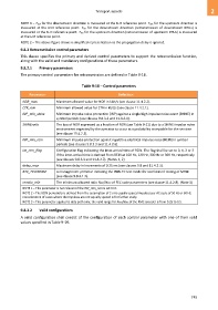
9.8.2.1 Primary parameters
The primary control parameters for retransmission are defined in Table 9-18.
Table 9-18 – Control parameters
Parameter Definition
NDR_max Maximum allowed value for NDR in kbit/s (see clause 11.4.2.2).
ETR_min Minimum allowed value for ETR in kbit/s (see clause 11.4.2.1).
INP_min_shine Minimum impulse noise protection (INP) against a single high impulse noise event (SHINE) in
symbol periods (see clauses 9.8.3.3 and 11.4.2.4).
SHINEratio The loss of NDR expressed as a fraction of NDR (see Table 9-21) due to a SHINE impulse noise
environment expected by the operator to occur at a probability acceptable for the services
(see clause 11.4.2.5).
INP_min_rein Minimum impulse protection against repetitive electrical impulse noise (REIN) in symbol
periods (see clauses 9.8.3.3 and 11.4.2.6).
iat_rein_flag Configuration flag indicating the inter-arrival time of REIN. The flag shall be set to 0, 1, 2 or 3
if the inter-arrival time is derived from REIN at 100 Hz, 120 Hz, 300 Hz or 360 Hz, respectively
(see clauses 9.8.3.3 and 11.4.2.7). (Notes 1, 2)
delay_max Maximum delay in increments of 0.25 ms (see clauses 9.8 and 11.4.2.3).
RTX_TESTMODE A management primitive initiating the PMS-TC test mode for accelerated testing of MTBE
(see clause 9.8.3.1.2).
rnratio_min The minimum allowed ratio RFEC/NFEC of FEC code parameters (see clause 11.4.2.8). (Note 3)
NOTE 1 – This parameter is not relevant if the INP_min_rein is set to 0.
NOTE 2 – The REIN periodicity is derived from the assumption of 2 or 6 equally spaced impulses per AC cycle of 50 Hz or 60 Hz.
Consideration of cases where the impulses are not equally spaced is for further study.
NOTE 3 – This parameter applies to data path only; the valid range for R FEC/N FEC of the RMC encoder is from 0.25 to 0.5.
9.8.2.2 Valid configurations
A valid configuration shall consist of the configuration of each control parameter with one of their valid
values specified in Table 9-19.
745