
Page 619 - 5G Basics - Core Network Aspects
P. 619
Transport aspects 2
transmission performance. In this measurement, a 64-QAM was employed as a modulation format of the
OFDM subcarrier. To generate a desired RoF signal, the generated LTE signals were input into the RoF Tx,
which corresponded to an OLT.
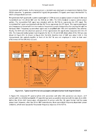
The generated RoF signal with a centre wavelength of 1 550 nm and an optical power of about 5 dBm was
transmitted over the 20 km SMF and the VOA to an ONU. The VOA emulated a passive optical power
splitter. The transmitted RoF signal was detected with the RoF Rx to regenerate the LTE signal. The
transmitted RoF signal was detected with the RoF Rx to regenerate the LTE signal. This regenerated signal
was frequency-up-converted from intermediate frequencies to radio frequencies after passing through the
bandpass filter. Frequency-up-converted signal was re-amplified with HPA and inputted to the antenna.
Finally, the EVM and the electrical spectrum of the regenerated LTE signal were measured with the LTE
VSA. The measured optical power level diagrams for 10, 15, 20 and 25 dB attenuation of the VOA are also
shown in Figure 9-8. As shown in Figure 9-8, the total insertion loss of SMF was about 5 dB. In this
measurement, the optical amplifier in front of the RoF Rx was not employed in order to take cost-
effectiveness of the ONU into account.
Figure 9-8 – Typical experimental set-up (upper) and optical power level diagram (lower)
In Figure 9-9, measured RF spectra before E/O conversion and after O/E conversion are shown. 12 IF
carriers with the 20 MHz bandwidth LTE signal format were successfully obtained with the help of an AWG.
Before the 20 km SMF transmission, all generated IF carriers with the LTE signal format had the same
power level. However, after the 20 km SMF transmission, there were slight frequency-dependent power
variations, which were caused by the uneven frequency response of the RoF Tx.
609