
Page 616 - 5G Basics - Core Network Aspects
P. 616
2 Transport aspects
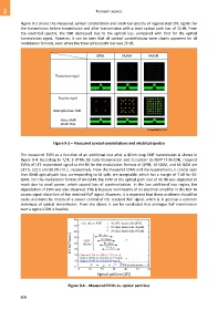
Figure 9-3 shows the measured symbol constellation and electrical spectra of regenerated LTE signals for
the transmission before transmission and after transmission with a total optical path loss of 32 dB. From
the electrical spectra, the SNR decreased due to the optical loss, compared with that for the optical
transmission signal. However, it can be seen that all symbol constellations were clearly apparent for all
modulation formats, even when the total optical path loss was 20 dB.
QPSK 16QAM 64QAM
Transmission signal
Receiver signal
Total optical loss: 32dB
40-km SMF
20-dB VOA
G Suppl.55(15)_F9-3
Figure 9-3 – Measured symbol constellations and electrical spectra
The measured EVM as a function of an additional loss after a 40 km-long SMF transmission is shown in
Figure 9-4. According to "LTE; E-UTRA; BS radio transmission and reception" [b-3GPP TS 36.104], required
EVMs of LTE transmitted signal at the BS for the modulation formats of QPSK, 16-QAM, and 64-QAM are
≤17.5, ≤12.5 and ≤8.0% r.m.s., respectively. From the measured EVMs and the requirements, it can be seen
that 30 dB optical path loss, corresponding to 64 split, are acceptable, which has a margin of 7 dB for 64-
QAM. For the modulation format of 64-QAM, the EVM at the optical path loss of 42 dB was degraded so
much due to small power, which caused loss of synchronization. In the low additional loss region, the
degradation of EVM was also observed. This is because nonlinearity of an electrical amplifier in the RoF Rx
causes signal distortion of the received RoF signal. However, it is expected that these problems should be
easily overcome by means of a power control of the received RoF signal, which is in general a common
technique of optical transmission. From the above, it can be concluded that analogue RoF transmission
over a typical ODN is feasible.
Figure 9-4 – Measured EVMs vs. optical path loss
606