
Page 1196 - 5G Basics - Core Network Aspects
P. 1196
2 Transport aspects
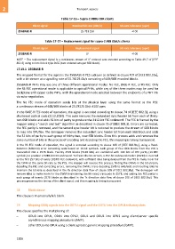
Table 17-16 – Supra-2.488G CBR clients
Client signal Nominal bit rate (kbit/s) Bit-rate tolerance (ppm)
25GBASE-R 25 781 250 100
Table 17-17 – Replacement signal for supra-2.488 Gbit/s clients
Client signal Replacement signal Bit-rate tolerance (ppm)
25GBASE-R LF 100
NOTE – The replacement signal is a continuous stream of LF ordered sets encoded according to Table 49-7 of [IEEE
802.3] using control block type 0x55 (two ordered sets per 66B block).
17.13.1 25GBASE-R
The mapped format for the signal is the 25GBASE-R PCS sublayer as defined in clause 107 of [IEEE 802.3by],
with a bit-stream at a signalling rate of 25.78125 Gb/s consisting of 64B/66B encoded blocks.
25GBASE-R PHYs may use one of three different operational modes: No FEC, BASE-R FEC, or RS FEC. Only
the RS FEC operational mode is applicable to optical PHYs, while any of the three modes may be used for
backplane and copper cable PHYs, with the operational mode selected between the endpoints of a PHY link
via auto-negotiation.
The No FEC mode of operation sends bits at the physical layer using the same format as the PCS:
a continuous stream of 64B/66B blocks at 25.78125 Gb/s ±100 ppm.
In the BASE-R FEC mode of operation, the signal is encoded according to clause 74 of [IEEE 802.3], using a
shortened cyclical code (2112,2080). This code removes the redundant sync header bit from each of thirty-
two 66B blocks and adds 32 bits of parity to produce the 2112-bit FEC codeword. The FEC is framed by the
mapper using a "search and test" algorithm as described in clause 73 of [IEEE 802.3]. Errors are corrected,
the FEC parity is removed, and the second sync header bit is restored to produce the stream of 66B blocks
to map into OPUflex. The demapper removes the redundant sync header bit from each 66B block and adds
the 32 bits of parity to each group of thirty-two, now 65B blocks. Since this process adds and removes the
same number of bits in the process of encoding and decoding the FEC, this mapping is timing transparent.
In the RS FEC mode of operation, the signal is encoded according to clause 108 of [IEEE 802.3by], using a Reed-
Solomon (528,514) error correcting code based on 10-bit symbols. Each group of four 66B blocks from the PCS is
transcoded into a 257B block. Twenty 257B blocks (5140 bits) are combined with 140 bits of FEC parity (14 FEC
symbols) to produce a 5280-bit FEC codeword. To frame the bit-stream, a 257-bit codeword marker (CWM) is inserted
as the first 257 bits of every 1024th FEC codeword, with sufficient idles being deleted from the PCS to make room for
the CWM at the same bit-rate as the PCS. The mapper will reverse this process, finding the CWMs in the bit-stream,
decoding the FEC and correcting errors, removing the CWMs, trans-decoding 257B to 64B/66B, and inserting idles to
maintain the bit-rate as described in the Rx direction data flow of clause 108 of [IEEE 802.3by]. The demapper will
remove idles to make room for the CWM (maintaining the bit-rate), transcode to 257B, and adding the FEC parity to
each group of twenty 257B blocks as described in the Tx direction data flow of clause 108 of [IEEE 802.3by]. This
process preserves the timing of the client signal, and this mapping is timing transparent.
18 Blank clause
This clause is intentionally left blank.
19 Mapping ODUj signals into the ODTU signal and the ODTU into the OPUk tributary slots
This clause specifies the multiplexing of:
– ODU0 into OPU1, ODU1 into OPU2, ODU1 and ODU2 into OPU3 using client/server specific
asynchronous mapping procedures (AMP);
– other ODUj into OPUk using a client agnostic generic mapping procedure (GMP).
1186