
Page 1191 - 5G Basics - Core Network Aspects
P. 1191
Transport aspects 2
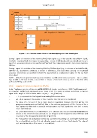
Figure 17-19 OPUflex frame structure for the mapping of a FlexE client signal
During a signal fail condition of the incoming FlexE client signal (e.g., in the case of a loss of input signal),
this failed incoming FlexE client signal is replaced by a stream of 66B blocks, with each block carrying one
local fault sequence ordered set (as specified in [FlexE IA]). This replacement signal is then mapped into the
OPUflex.
During a signal fail condition of the incoming ODUflex/OPUflex signal (e.g., in the case of an ODUflex-AIS,
ODUflex-LCK, ODUflex-OCI condition), a stream of 66B blocks, with each block carrying one local fault
sequence ordered sets (as specified in [FlexE IA]) is generated as a replacement signal for the lost FlexE
client signal.
NOTE 1 – A FlexE client signal local fault sequence ordered set is a 66B control block (sync header = 10) with a block
type of 0x4B, an "O" code of 0x00, a value of 0x01 to indicate a "local fault" in lane 3, and all of the other octets
(before scrambling) equal to 0x00.
17.12 Mapping of FlexE aware signals into OPUflex
In the FlexE aware service p (1 ≤ p ≤ m ≤ 252) 100G FlexE signals – out of an m × 100G FlexE Group signal –
are crunched, padded and interleaved as per Figure 17-20. This results in a FlexE partial rate (sub)group
signal with a length of 1024*n blocks, with n = n1 + n2 + .. + np (FlexEp-n):
– i = 1 .. p represent the FlexE signals in ascending PHY number order.
– ni (i = 1..p) represents the number of FlexE calendar slots that are to be transferred.
– The value of ni for each of the p FlexE signals is negotiated between the FlexE partial rate
(sub)group mapping port and the FlexE Shim in the customer equipment. q (0 ≤ q ≤ p) out of the p
FlexE signals may have their ni set to 20 while the other p-q FlexE signals may have their ni set to
values lower than 20.
– Bits of the Ethernet error control blocks in 20-ni calendar slots that are marked unavailable are
located at the end of the sub-calendar and are dropped by the mapper to reduce the rate and
reinserted by the demapper to restore the original rate.
– The FlexE partial rate (sub)group interleaving is simplified by adding ni-1 padding blocks between
the overhead block and the first sub-calendar block in each of the p FlexE signals. The value of
each padding block is an Ethernet error control block.
1181