
Page 1195 - 5G Basics - Core Network Aspects
P. 1195
Transport aspects 2
17.13 Mapping a 64b/66b PCS coded signal into OPUflex using BMP and 2-bit alignment of 66b code
words
Mapping of a 64b/66b PCS coded (xGBASE-R) client signal (with up to 100 ppm bit-rate tolerance) into an
OPUflex is performed by a bit-synchronous mapping procedure (BMP). Table 17-16 specifies the clients
defined by this Recommendation.
The bit-synchronous mapping process deployed to map constant bit rate client signals into an OPUflex does
not generate any justification control signals.
The 66b block stream of the xGBASE-R client signal shall be scrambled before mapping into the OPUflex. In
the reverse operation, following termination of the OPUflex signal, the 66 block stream will be descrambled
after demapping from the OPUflex.
39
58
A self-synchronizing scrambler with generator polynomial 1+ x +x shall be used, that is identical to the
scrambler specified in clause 49.2.6 of [IEEE 802.3]. 66b block stream scrambling is required to provide
security against false 66b block delineation (as the two sync header bits bypass the scrambler), the 66b
codewords replicating the OTU and ODU frame alignment signal and the 66b codewords combined with the
OTU scrambler pattern used for the interface replicating the OTU and ODU frame alignment signal.
The OPUflex clock for the bit-synchronous mapping is derived from the client signal. During a signal fail
condition of the incoming client signal (e.g., in the case of a loss of input signal), this failed incoming signal
is replaced by the appropriate replacement signal as defined in Table 17-17. The OPUflex payload signal bit
rate shall be within the limits specified in Table 7-3 and the limits defined in [ITU-T G.8251] and no frame
phase discontinuity shall be introduced in this case and when resynchronization on the incoming client
signal.
During a signal fail condition of the incoming ODUflex/OPUflex signal (e.g., in the case of an ODUflex-AIS,
ODUflex-LCK, ODUflex-OCI condition), the failed client signal is replaced by the appropriate replacement
signal as defined in Table 17-17.
The OPUflex overhead for this mapping consists of:
– a payload structure identifier (PSI) including the payload type (PT) as specified in Table 15-9, the
client signal fail (CSF) and 254 bytes plus 7 bits reserved for future international standardization
(RES);
– seven bytes reserved for future international standardization (RES).
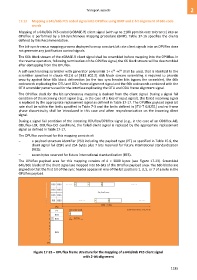
The OPUflex payload area for this mapping consists of 4 3808 bytes (see Figure 17-23). Scrambled
64b/66b blocks of the client signal are mapped into 66-bits of the OPUflex payload area. The 66b blocks are
aligned so that the first bit of the sync header appears in one of the bit positions 1, 3, 5, or 7 of a byte in the
OPUflex payload.
Figure 17-23 – OPUflex frame structure for the mapping of a 64b/66b PCS client signal
with 2-bit alignment
1185