
Page 1193 - 5G Basics - Core Network Aspects
P. 1193
Transport aspects 2
As shown in the Figure 17-22, a value of n = m =128 (16-Byte) is chosen. Given the deterministic generation
of the stuffing, only two C128(t) values are used for this mapping (C128 = 948 or 949). Generating C128 = 949
(vs. C128 = 948) is deterministic at the source (s = 3373/23384, 15-bit sigma-delta).
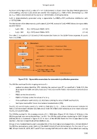
Cm(t) is deterministically generated using a sigma-delta Cm=948/Cm=949 justification distribution with
s = 3373/23384:
The distribution of the deterministic justification (Cm(t)= 948, instead of Cm(t) =949) follows the sigma-delta
equation below:
– Cm(t) = 948 if (j × 3373) mod 23384 < 3373 (17-13)
– Cm(t) = 949 if (j × 3373) mod 23384 ≥ 3373 (17-14)
The index 'j' in equations (17-13) and (17-14) enumerates frames in the 23384 frame sequence. It counts
from 1 to 23384.
Figure 17-21 – Sigma-delta accumulator for deterministic justification generation
The OPUflex overhead for this mapping consists of a:
– payload structure identifier (PSI) including the payload type (PT) as specified in Table 15-9, the
client signal fail (CSF) and 253-p bytes plus 7 bits reserved for future international standardization
(RES);
– PSI[3] carries the value of p
– PSI[4] to PSI[3+p] carries the values of n1 to np
– three justification control (JC1, JC2, JC3) bytes carrying the value of GMP overhead Cm;
– four bytes reserved for future international standardization (RES).
The JC1, JC2 and JC3 bytes consist of a 14-bit Cm field (bits C1, C2, .., C14), a 1-bit increment indicator (II)
field, a 1-bit decrement indicator (DI) field and an 8-bit CRC-8 field which contains an error check code over
the JC1, JC2 and JC3 fields.
The OPUflex payload for this mapping consists of 4 3808 bytes (Figure 17-22). Blocks of 16 bytes in the
OPUflex payload area are numbered from 1 to 952. The OPUflex payload byte numbering for GMP 16-byte
(128-bit) blocks is illustrated in Figure 17-22. In row 1 of the OPUflex frame the first 16-byte block will be
labelled 1, the next 16-byte block will be labelled 2, etc.
Groups of one hundred twenty-eigth successive bits of the client signal are mapped into a 16-byte block of
the OPUflex payload area under control of the BGMP data/stuff control mechanism. For the case of C128 =
948, 16 byte blocks #1, #239, #477 and #715 are carrying stuff bits and the other 16-bye blocks are carrying
1183