
Page 318 - Kaleidoscope Academic Conference Proceedings 2024
P. 318
2024 ITU Kaleidoscope Academic Conference
Figure 1 – Energy diagram of Praseodymium ions showing pumping at 1017 nm (green), stimulated absorption and emission
in O-band (blue), other radiative transitions (blue dot) donor-acceptor transitions (light-pink) and non-radiative transitions
(red).
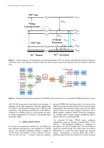
Figure 2 – Diagram illustrating the integration of the PDFA at the system level in a five-channel CWDM transmission system.
with 700 mW pump power using bidirectional pumping. It generator (PRBS) feeds the logical data to the return-to-zero
optimizes all the PDF parameters with gain ranging from (NRZ) pulse generator which converts it into electrical signal.
25.23 dB to 44.56 dB and NF ranging from 4.1 dB to 8.2 dB Subsequently, these electrical signals along with the optical
respectively. The transmission performance of the PDFA is signals emitted by the lasers undergo modulation with a
evaluated in a CWDM system as a pre-amplifier and offers Mach–Zehnder modulator (MZM). Following modulation,
an errorless transmission over 90 km of conventional single the resulting optical signals undergo multiplexing (MUX)
mode-fiber (SMF). and are sent over a conventional SMF.
The combined 50 Gbps CWDM signal, undergoes
2. SIMULATION SETUP amplification using the proposed O-band PDFA. At the
receiver, a De-multiplexer (DEMUX) is employed to
To evaluate the transmission performance, the PDFA has demultiplex the optical CWDM signal. The demultiplexed
been optimized and placed as a pre-amplifier in a CWDM signals are passed through PIN diodes which are used as
system. The schematic illustrated in Figure 2 consists of photodectors to convert the optical signals into electrical
five CW lasers of wavelengths 1276 nm, 1296 nm, 1316 nm, signals. Subsequently, a low-pass Bessel filter (LPF) is
1336 nm and 1356 nm . A pseudo random bit sequence applied to reduce band noise and harmonics before the signal
– 274 –