
Page 1299 - 5G Basics - Core Network Aspects
P. 1299
Transport aspects 2
Appendix VI
Parallel logic implementation of the CRC-9, CRC-8, CRC-5 and CRC-6
(This appendix does not form an integral part of this Recommendation.)
CRC-9
9
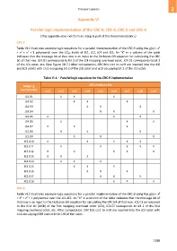
Table VI.1 illustrates example logic equations for a parallel implementation of the CRC-9 using the g(x) = x
2
3
+ x + x + 1 polynomial over the CnD fields of JC1, JC2, JC4 and JC5. An "X" in a column of the table
indicates that the message bit of that row is an input to the Exclusive-OR equation for calculating the CRC
bit of that row. JC4.D1 corresponds to bit 2 of the JC4 mapping overhead octet, JC4.D2 corresponds to bit 3
of the JC4 octet, etc. (See Figure 20-7.) After computation, CRC bits crc1 to crc9 are inserted into the JC6
and JC3 octets with crc1 occupying bit 2 of the JC6 octet and crc9 occupying bit 2 of the JC3 octet.
Table VI.1 – Parallel logic equations for the CRC-9 implementation
Mapping CRC checksum bits
overhead bits
crc1 crc2 crc3 crc4 crc5 crc6 crc7 crc8 crc9
JC4.D1 X X X
JC4.D2 X X X
JC4.D3 X X X
JC4.D4 X X X
JC4.D5 X X X
JC4.D6 X X X
JC4.D7 X X X
JC1.D8 X X X
JC1.D9 X X X
JC5.D10 X X X X X
JC5.D11 X X X X X
JC5.D12 X X X X X
JC5.D13 X X X
JC5.D14 X X X
JC5.D15 X X X
JC5.D16 X X X
JC2.D17 X X X
JC2.D18 X X X
CRC-8
8
Table VI.2 illustrates example logic equations for a parallel implementation of the CRC-8 using the g(x) = x
3
2
+ x + x + 1 polynomial over the JC1-JC2. An "X" in a column of the table indicates that the message bit of
that row is an input to the Exclusive-OR equation for calculating the CRC bit of that row. JC1.C1 corresponds
to the first bit (MSB) of the first mapping overhead octet (JC1), JC1.C2 corresponds to bit 2 of the first
mapping overhead octet, etc. After computation, CRC bits crc1 to crc8 are inserted into the JC3 octet with
crc1 occupying MSB and crc8 the LSB of the octet.
1289