
Page 1257 - 5G Basics - Core Network Aspects
P. 1257
Transport aspects 2
and
f client B server
C n t int (D-7)
f
server n
As the client data has to fit into the payload area of the server signal, the maximum value of Cn and as such
the maximum client bit rate is limited by the size of the server payload area.
C n Pt server (D-8)
P server
f client f server n (D-9)
B server
Pserver: maximum number of (n bits) data entities in the server payload area
The client and server bit rate are independent. This allows specifying the server bit rate independently from
the client bit rates. Furthermore, client clock impairments are not seen at the server clock.
If the client or server bit rate changes due to client or server frequency tolerances, cn and Cn(t) change
accordingly. A special procedure has to take care that Cn(t) is changed fast enough to the correct value
during start-up or during a step in the client bit rate (e.g., when the client signal is replaced by its AIS signal
or the AIS signal is replaced by the client signal). This procedure may be designed to prevent buffer over-
/underflow, or an additional buffer over-/underflow prevention method has to be deployed.
A transparent mapping has to determine Cn(t) on a server (multi)frame per (multi)frame base.
In order to extract the correct number of client information entities at the de-mapper, Cn(t) has to be
transported in the overhead area of the server frame or multiframe from the mapper to the de-mapper.
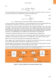
Figure D.1 shows the generic functionality of the mapper and de-mapper circuit.
At the mapper, Cn(t) is determined based on the client and server clocks. The client data is constantly
written into the buffer memory. The read out is controlled by the value of Cn(t).
At the de-mapper, Cn(t) is extracted from the overhead. Cn(t) controls the write enable signal for the buffer.
The client clock is generated based on the server clock and the value of Cn(t).
Cn(t) has to be determined first, then it has to be inserted into the overhead and afterwards Cn(t) client data
entities have to be inserted into the payload area of the server as shown in Figure D.2.
Data Server Server data Client data
Client data OH data OH Buffer
Write
Buffer C n insertion extraction enable and
and Read generate Client clock
Client clock determine C n enable C n client clock
Server clock Server clock
Read Read
control control
a) Mapper b) De-mapper G.709-Y.1331(12)_FD.1
Figure D.1 – Generic functionality of a mapper/de-mapper circuit
1247