
Page 1253 - 5G Basics - Core Network Aspects
P. 1253
Transport aspects 2
Annex C
Adaptation of OTU3 and OTU4 over multichannel parallel interfaces
(This annex forms an integral part of this Recommendation.)
NOTE 1 – This mechanism is designed to allow the use of the optical modules being developed for IEEE 40GBASE-R and
100GBASE-R signals for short-reach client-side OTU3 and OTU4 interfaces respectively. The corresponding physical
layer specifications are being added to [ITU-T G.695] and [ITU-T G.959.1].
OTU3 signals may be carried over parallel interfaces consisting of four lanes. This four lane format is referred to as the
OTL3.4 format.
OTU4 signals may be carried over parallel interfaces consisting of four or ten lanes, which are formed by bit
multiplexing of 20 logical lanes. The four lane format is referred to as the OTL4.4 signal format and the ten lane format
is referred to as the OTL4.10 signal format.
NOTE 2 – Ten lane IEEE 100GBASE-R interfaces have no corresponding ITU-T physical layer interface specification.
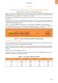
The OTU3 and OTU4 frames are inversely multiplexed over physical/logical lanes on a 16-byte boundary aligned with
the OTUk frame as illustrated in Figure C.1. The OTUk frame is divided into 1020 groups of 16-bytes.
1 4080
1 1:16 (FAS) 17:32 33:48 49:64 4065:4080
2 4081:4096 4097:5012 5013:5028 5029:5044 9145:9160
3 9161:9176 9177:9192 9193:9208 9209:9224 12225:12240
4 12241:12256 12257:12272 12273:12288 12289:13304 16305:16320
Figure C.1 – OTU3 and OTU4 frames divided on 16-byte boundary
OTU3 16-byte increment distribution
Each 16-byte increment of an OTU3 frame is distributed round robin, to each of the four physical lanes. On
each OTU3 frame boundary the lane assignments are rotated.
For OTU3, the lane rotation and assignment is determined by the two LSBs of the MFAS as described in
Table C.1 and Figure C.2, which indicates the starting group of bytes of the OTU3 frame that are sent on
each lane.
NOTE 3 – MFAS is scrambled as defined in clause 11.2.
The pattern repeats every 64 bytes until the end of the OTU3 frame. The following OTU3 frame will use
different lane assignments according to the MFAS.
Table C.1 – Lane rotation assignments for OTU3
MFAS 7-8 Lane 0 Lane 1 Lane 2 Lane 3
*00 1:16 17:32 33:48 49:64
*01 49:64 1:16 17:32 33:48
*10 33:48 49:64 1:16 17:32
*11 17:32 33:48 49:64 1:16
1243